-
Posts
8,045 -
Joined
-
Last visited
-
Days Won
71
Content Type
Profiles
Forums
Gallery
Downloads
Blogs
Events
Store
Aircraft
Resources
Tutorials
Articles
Classifieds
Movies
Books
Community Map
Quizzes
Videos Directory
Everything posted by red750
-
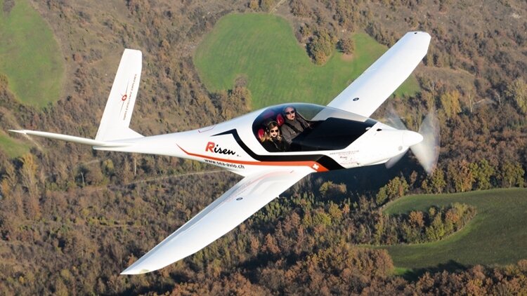
The Swiss Excellence Risen is a Swiss two-seat in side-by-side configuration, low wing ultralight aircraft, designed by Italian-Argentine aeronautical engineer Alberto Porto and produced by Swiss Excellence Airplanes. The aircraft was introduced at the 2015 AERO Friedrichshafen show. It is supplied ready-to-fly. The prototype was completed in 2012 and tested over the next three years before being publicly shown in 2015. The design entered production in mid-2015. The aircraft has a glass cockpit, motorized canopy, autopilot, retractable landing gear and a ballistic parachute. The main structure is made from carbon fibre. Available engines are 75 kW (100 hp) Rotax 912 ULS and Rotax 912 iS and the 86 kW (115 hp) Rotax 914 turbocharged powerplant. In 2020 the aircraft's gross weight was increased from 472.5 to 600 kg (1,041.7 to 1,322.8 lb). In 2016 the design set an FAI Class R (Microlights and paramotors) world speed record for absolute speed of 323.82 km/h (201 mph) with a standard Rotax 912 engine. For this record the pilot Alberto Porto, who is also the CEO of Swiss Excellence Airplanes, received an Oscar from VFR Magazine and the De la Vaulx Medal by the FAI. The FAI records table lists the Risen as having flown at the speed of 428.18 km/h (266 mph) over a straight course on Jan 22, 2023. Variants Swiss Excellence Risen Model with retractable landing gear Swiss Excellence Siren Model with fixed landing gear and revised cockpit arrangement.
-
When did you last fly around the world in an LSA, accompanied or otherwise?
-
He is the youngest at 15 for most of the journey.Turned 16 as he crossed the International Date Line on the final leg from USA to Australia.
-
Brisbane teenager Byron Waller landed his Sling TSi at Brisbane today, completing to an end his historic around the world flight as the youngest accompanied person to do so. He celebrated his 16th birthday as he crossed the International Date Line 2 days ago. The flight took 67 days. Back to school tomorrow, and now to get his learner drivers permit.
-
A Qantas charter Boeing 787-9 is making its way from Perth to Los Angeles, non-stop. QF315 departed just after 2:30am this morning (14 October) and is expected to land at 4am the same day, local time. Clocking in at 9,319 miles, Perth to Los Angeles is too long to be flown by Qantas' Boeing 787-9 non-stop as a regular commercial flight. Qantas lists the range of its Boeing 787s at 9,008 miles with a full payload – just enough to cover Perth-London. But as a charter flight with considerably less weight onboard, the Boeing 787 has the legs to fly much further! Once the Airbus A350-1000 ULR comes into service for Project Sunrise, Perth-Los Angeles could be a new permanent route to look out for.
-

Delta pilot refuses to fly Boeing 757 Atlanta 12/10/25
red750 replied to red750's topic in US/Canada General Discussion
If it's a Boeing, I ain't going. -
Passengers on Delta Flight DL466 from Atlanta to Las Vegas were stunned when their captain suddenly announced he was refusing to fly their assigned Boeing 757. The veteran pilot, with over 25 years of experience, revealed that he had flown the very same jet the day before and filed a maintenance request for a possible elevator issue—an essential control surface for safe flight. Despite a nine-hour inspection that cleared the aircraft, his “gut feeling” told him something wasn’t right. Walking off the jet bridge, he ordered boarding stopped, explained his decision over the PA, and declared he was rejecting the aircraft for safety reasons—something he said he hadn’t done in 22 years. Even his first officer admitted it was only the second time in his career he had rejected a plane. Though the decision caused more than an hour’s delay, passengers at the gate broke into applause, praising the captain’s transparency and commitment to safety. Delta quickly dispatched a replacement 757, and the flight eventually departed without issue. The incident highlighted the ultimate authority of the pilot-in-command, who by law has the final say on whether an aircraft is safe to fly. While the delay was inconvenient, the overwhelming sentiment was clear: passengers were grateful for a captain who put their lives ahead of the schedule.
- 12 replies
-
- 11
-

-

-

-
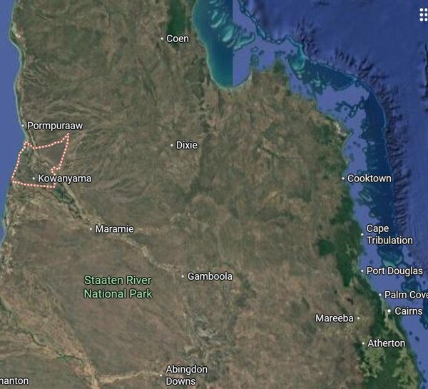
A 27-year-old pilot has died in a helicopter crash in Far North Queensland. Emergency services launched a search and rescue operation after the Robinson R22 helicopter failed to return to its homestead at Yagoona near Kowanyama at 7.30pm yesterday. The Australian Maritime Safety Authority Challenger Jet and Rescue 510 helicopter were deployed to search for the missing aircraft. The helicopter was found at 8.30am today about seven kilometres south-east of Yagoona. The pilot was the sole occupant of the aircraft and he has not been formally identified. The Queensland Police forensic crash unit will prepare a report for the coroner. The Australian Transport Safety Bureau is also investigating.
-
Did you not read the first paragraph of the opening post?
-
Different EVTOL, but interesting video - Jetson 1. 96K views · 2.8K reactions | Jetson ONE Takes Flight at UP.Summit... WWW.FACEBOOK.COM Jetson ONE Takes Flight at UP.Summit 2025! Part 1 🚀 In front of a breathtaking crowd of 20,000 spectators, we showcased our 4-ship airshow display ending with a solo flight demonstration of the...
-
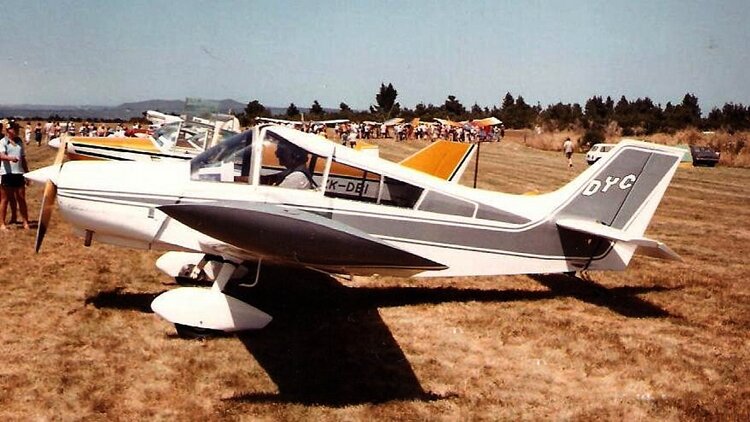
The MacFam Cavalier is a homebuilt aircraft designed by Stan McLeod, developed through a progressing series of models, all using all-wooden construction. The model range includes the SA102, SA102.5, SA103, SA104 and the SA105. The Cavalier was a new design based on the French wooden homebuilt GY-20 Minicab designed by Yves Gardan in 1949. The plans were translated from French to English and modified by Stan McLeod. The plans were marketed by K&S Aircraft of Calgary, Alberta and later MacFam. The Cavalier is a two-seat side-by-side configuration homebuilt that uses all-wood construction. The landing gear may be configured as fixed, or retractable, in tricycle or conventional layout. The wing uses a single box spar covered in 3/32" plywood leading edge skins. The entire wing is fabric covered. The early Cavalier SA102 series can accept any four cylinder aircraft engine ranging in weight up to 235 lb (107 kg) and 85 to 135 hp (63 to 101 kW), including the Continental O-200, Lycoming O-235 and Franklin 4AC. Later series can use larger engines. SA102 options included wing tip tanks and a third jump seat. Variants SA102 1963 Interchangeable tricycle gear to conventional gear configuration with sliding canopy.[6] SA102.5 1968 model SA103 Conventional gear version of Super Cavalier SA104 Tricycle gear version of Super Cavalier SA105 Super Cavalier (Specifications below) 1968 model retractable tricycle gear model. Engineered for larger 200hp engines.
-
-
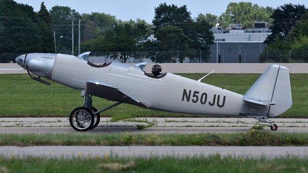
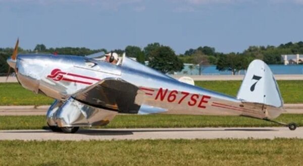
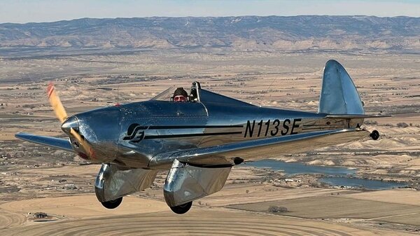
Every year, EAA AirVenture Oshkosh is full of surprises. In 2025, there was none bigger than the Spirit Engineering SE-1. Kept tightly under wraps, four SE-1s made the journey from Grand Junction, Colorado, to Oshkosh to debut the design on the world’s biggest stage. The four SE-1s arrived at Oshkosh after burning a total of 88 gallons of fuel, and the aircraft have been the buzz of the convention. Priced at US$69,500 out the door, the special light-sport aircraft (S-LSA) draws attention with its design that is reminiscent of aviation’s classics. Think Luscombe, Ryan ST, or Swift. There are insufficient details to create a profile of the aircaft just yet, even on the company website. However, here are a couple of photos and a video.
-
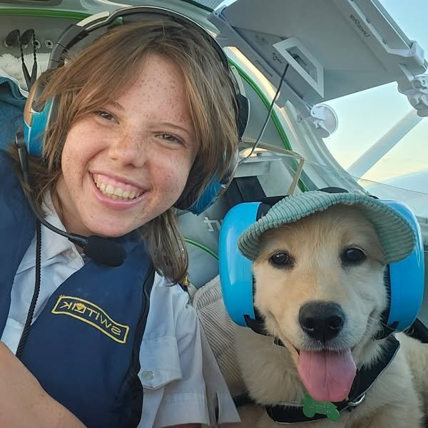
From RAA Facebook page. MEET OUR NEW YOUTH AMBASSADOR: JENNIFER We are thrilled to celebrate Jennifer, our new Youth Ambassador for Recreational Aviation Australia, who has just made history as the youngest female pilot to fly around Australia. At only 15 years old, Jennifer has achieved what many only dream of, showing remarkable skill, determination, and passion for aviation.
-
- 5
-

-

R22 crash Bankstown 3 October.
red750 replied to flying dog's topic in Aircraft Incidents and Accidents
https://7news.com.au/news/man-dead-and-teen-fighting-for-life-as-helicopter-crashes-onto-car-near-bankstown-in-sydney-c-20225294 -
If you’ve ever wondered how an Air Force pilot becomes a member of the Roulettes, this is for you! In mid-2024 three new pilots joined the team, get to know the pilots as they learn to fly the manoeuvres for their first display at the 2024 Pacific Airshow on Queensland’s Gold Coast. ‘Australian Roulette’ on 9Go! and streaming on 9Now
-
-
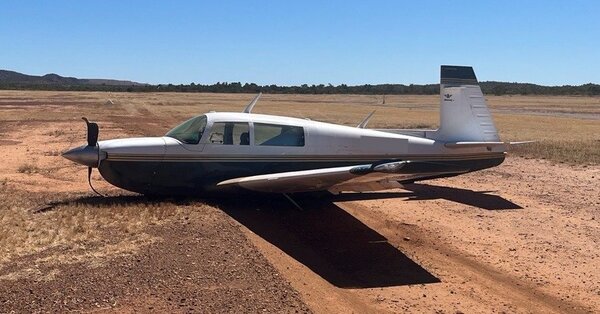
A new ATSB occurrence brief details a wheels-up landing involving a Mooney M20J at Mt Isa Airport. --What happened-- On 20 August 2025, a Mooney M20J, with a pilot and 2 passengers on board, was landing at Mount Isa Airport, Queensland following a private flight. The pilot reported that, at the time, the wind was gusty with some crosswind on the airport’s single runway. After discontinuing the first landing attempt, the pilot circled and conducted a second approach, targeting a landing speed of 65–70 kt. Subsequently, the aircraft landed and began to decelerate. Consistent with their normal procedure, the pilot raised the flap and turned off the fuel pump. The pilot reported that they then mistakenly moved the landing gear lever from the down to the up position. As a result, the landing gear started to retract while the aircraft was on the runway. Recognising the situation, the pilot applied full power and raised the nose, resulting in the aircraft becoming airborne again. The aircraft banked left and climbed briefly before the pilot lowered the nose. The aircraft subsequently impacted the ground to the left of the runway and slid for several metres before coming to a stop. The pilot and passengers exited the aircraft without injuries, and the aircraft was substantially damaged. The aircraft’s maintenance manual stated that the aircraft was equipped with an airspeed‑activated landing gear safety system that was designed to prevent the gear from retracting when the aircraft was below 60 kt (±5 kt) indicated airspeed and airspeed was increasing. The manual further advised that when landing, the system may not engage until below 50 kt, and could allow the landing gear to retract if the gear switch was placed in the up position during the landing roll. --Safety message-- This accident serves as a reminder to pilots that incidents and accidents can occur at any time during the operation of an aircraft, including the landing roll. Maintaining awareness, in conjunction with the consistent use of procedures, checklists and flows, minimises the opportunity for inadvertent or mistaken manipulation of an aircraft’s controls or systems. --About this report-- Decisions regarding whether to conduct an investigation, and the scope of an investigation, are based on many factors, including the level of safety benefit likely to be obtained from an investigation. For this occurrence, no investigation has been conducted and the ATSB did not verify the accuracy of the information. A brief description has been written using information supplied in the notification and any follow-up information in order to produce a short summary report, and allow for greater industry awareness of potential safety issues and possible safety actions.
-
On the subject of the GF. When students at Warringa Park School, Werribee South, heard that Snoop Dogg was coming to Melbourne, they invited him to come to their school. What began as a long-shot Instagram post turned into something unforgettable — that dream came true. Snoop arrived at the Werribee South campus, joined the students in the studio, and recorded vocals for their track. He even took time to write his own lyrics, record in one take, and celebrate with our school community. Many people criticised his choice by the AFL, but he seems like a cool guy.
-
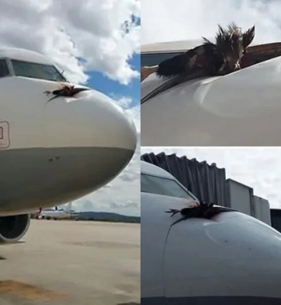
Hitching a ride on this thread. This appeared on Facebook today. No mention of location, airline or aircraft, just the pictures.


