red750
-
Posts
8,236 -
Joined
-
Last visited
-
Days Won
78
Content Type
Profiles
Forums
Gallery
Downloads
Blogs
Events
Store
Aircraft
Resources
Tutorials
Articles
Classifieds
Movies
Books
Community Map
Quizzes
Videos Directory
Everything posted by red750
-

Spitfire Gear up @ Scone, 26 March 2026
red750 replied to KRviator's topic in Aircraft Incidents and Accidents
I flew Piper Arrows and Bonanzas, never had a problem. -
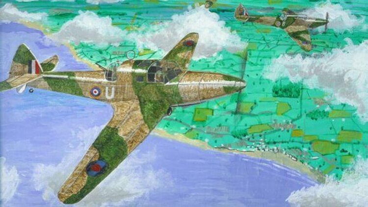
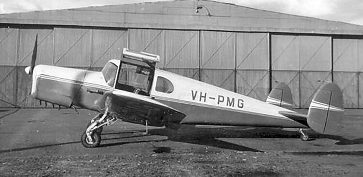 The Miles M.28 Mercury was a British aircraft designed to meet the need for a training and communications plane during the Second World War. It was a single-engined monoplane of wooden construction with a twin tail and a tailwheel undercarriage with retractable main units. Originally, the M.28 had been planned as a replacement for the Whitney Straight and Monarch, but this was shelved when war broke out. In 1941, the project was revived in response to a requirement for a training and communications aircraft. The design was produced as a private venture by Ray Bournon using Miles' normal wooden construction. The resulting machine introduced several features not found on trainers: retractable undercarriage and trailing edge flaps amongst others. In the communications role, the M.28 had four seats and a range of 500 miles (800 km). The prototype first flew on 11 July 1941 and proved easy to fly, with light controls and a short landing run. Owing to Miles' heavy commitment to war-production, however, only six aircraft were built, of slightly varying specifications, the last being the Mercury 6 which first flew in early 1946. Examples of the type were operated in the United Kingdom, Denmark, Germany, Switzerland and Australia. Variants M.28 Mark I: First prototype – Two seat trainer, powered by 130 hp (97 kW) de Havilland Gipsy Major I engine. M.28 Mark II: Three seat trainer (with dual controls) powered by 140 hp (100 kW) de Havilland Gipsy Major IIA. One built 1942. Re-engined with 140 hp Blackburn Cirrus Major II and then with a 150 hp (110 kW) Cirrus Major III post-war. M.28 Mark III: Three seat trainer with triple controls for two students and one instructor, powered by 150 hp Cirrus Major 3 and with revised wing section. One built (PW937). M.28 Mark IV: Four seat communications aircraft powered by 145 hp (108 kW) Gipsy Major IIA. One built 1944. M.28 Mark V: Post-war four-seater powered by Cirrus Major III. Square rear windows. One built 1947. M.28 Mark VI: Post war four-seater powered by Cirrus Major III. Round rear windows. One built 1946.
 -
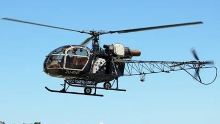 The Aérospatiale SA 315B Lama is a French single-engined helicopter. It combines the lighter Aérospatiale Alouette II airframe with Alouette III components and powerplant. The Lama possesses exceptional high altitude performance. The helicopters have been built under licence by Hindustan Aeronautics Limited (HAL) in India, known as the Cheetah; HAL later developed an upgraded variant, powered by the Turbomeca TM 333-2M2 engine, which is known as the Cheetal. An armed version, marketed as the Lancer, was also produced by HAL. It was also built under licence by Helibras in Brazil as the Gavião. The SA 315B Lama was originally designed to meet a Nepalese Army Air Service and Indian Air Force requirement for a rotorcraft capable of undertaking operations at hot and high conditions. Both countries possessed extreme mountain ranges in the form of the Himalayas in which even relatively powerful medium-sized helicopters could not be effectively operated within, thus there was an expressed desire for an aerial vehicle capable of operating in this challenging environment. To achieve the desired performance, Aerospatiale elected to combine elements of two existing popular helicopters in their inventory, the Aérospatiale Alouette II and the Aérospatiale Alouette III to produce a new rotorcraft specialised for high altitude performance. Specifically, the new helicopter, named Lama, was equipped with the Alouette III's Turbomeca Artouste turboshaft powerplant and its dynamic systems, and was furnished with a reinforced version of the Alouette II's airframe. On 17 March 1969, the first SA 315B, powered by an Artouste IIB engine, undertook its maiden flight. On 30 September 1970, the type received its airworthiness certificate, and it was introduced to operational service in July 1971. Due to its favourable high altitude performance, the Lama quickly became popular with operators worldwide, often being deployed within mountainous environments. As with the Alouette series, the type can be fitted for various roles, such as light passenger transport, agricultural tasks, oil-and-gas exploration, aerial firefighting, and other specialised duties. The military variants of the Lama include liaison, observation, photography, air/sea rescue, transport and ambulance duties. The SA315B is particularly suited to mountainous areas due to its performance and can carry underslung loads of up to 1000 kg (2,205 lb). By December 1976, 191 Lamas had been ordered by 68 operators. A large proportion of all SA 315B Lamas to be manufactured were produced under licence in India by Hindustan Aeronautics Limited (HAL), under the name Cheetah. More than three decades after production in India began, HAL was still receiving export orders for the original Cheetah. Along with the Alouette III, the Cheetah was a key product for HAL; experience from manufacturing the type aided in the later development of more advanced indigenous helicopters such as the HAL Dhruv. During the 1990s, HAL developed an armed light attack helicopter based upon the Cheetah, which was given the name Lancer. In 2006, HAL proposed a modernised variant to the Indian Army, designated as Cheetal, the principal change of which was the adoption of a modern, more powerful Turbomeca TM 333-2M2 powerplant in the place of the Artouste; HAL promoting the Cheetal's capabilities for operating in high altitude environments, such as the Siachen Glacier. Other improvements include new warning indicates, a cockpit voice recorder, flight monitoring system, artificial horizon, and modernised electronics. In 2006, an initial 10 Cheetals were ordered by the Indian Air Force. In February 2013, it was announced that the Indian and Nepalese Armies had signed a 300 crore (~US$55 million) contract for the urgent procurement of a further 20 Cheetals. For operational history and 5 variants, click here.
 -
 The de Havilland DH.93 Don was a 1930s British multi-role three-seat training aircraft built by de Havilland Aircraft. The Don was designed to meet Air Ministry Specification T.6/36 for a multi-role trainer and was a single-engined monoplane of wooden stressed-skin construction. The DH.93 Don was intended to be a trainer for pilots and radio operators, and as a gunnery trainer, the gunnery requirement involved the mounting of a dorsal gun turret. Student pilot and instructor sat side by side up front, while accommodation for a trainee WT (radio) operator and the turret gunner was behind in the cabin. The prototype with test marks E-3 (later military serial number L2387) first flew on 18 June 1937 and was transferred to RAF Martlesham Heath for official evaluation. In the course of the trials, more equipment was added which increased the weight, and as a result, in an attempt to reduce weight, the dorsal turret was removed. The aircraft was also modified with small auxiliary fins fitted beneath the tailplane. Despite the changes incorporated from the fifth aircraft, the type was deemed not suitable for training and the original order for 250 aircraft was reduced to only 50 aircraft, 20 of which were delivered as engineless airframes for ground training. The remaining aircraft served as communications and liaison aircraft, serving with No. 24 Sqn and numerous RAF Station Flights throughout the UK until early 1939, but all were grounded for use as instructional airframes in March 1939.
 -
Hi Jesse, Welcome to the forum. Just so you know, this is an Australian based forum despite having a .com URL, but we are open to all aviation people from around the globe and have members from many nations. While comments are predominantly Australia centred, we have members in America, Europe, Africa and so on. Feel free to join in the conversations. Cheers,
-
The company responsible for the highly criticised BOM website wins a $16 million tender to build a new climate data website for the government. Technology company Accenture Australia, which was also contracted for BOM's $96 million redesign, has been tasked with building a "platform service" for the Australian Climate Service over the next three years. Read more: Company that built highly criticised BOM website wins $16m contract for new site - ABC News WWW.ABC.NET.AU The company responsible for the highly criticised BOM website wins a $16 million tender to build a new climate data website for the government.
-
A light aircraft carrying seven people crashed into shallow waters in Roebuck Bay near Broome, Western Australia, on Thursday, March 19, 2026, shortly after taking off from Broome Airport around 11:25 a.m. The plane, a Cessna 441 Conquest, experienced a loss of engine power soon after departure and went down in the mangrove-fringed area known as Fisherman Bend. All seven people on board — two pilots and five passengers — survived the crash. One individual sustained minor head injuries and was airlifted to hospital, while the others were treated at the scene and also taken to Broome Hospital with non-life-threatening injuries. Emergency services, including marine rescue, police, and St John Ambulance, responded swiftly, with one person being winched from the wreckage by helicopter. The Australian Transport Safety Bureau (ATSB) has launched a formal investigation into the incident. Investigators are examining the wreckage, recovering flight data, and interviewing crew, passengers, and witnesses. The aircraft was en route to Mungalalu Truscott Airport, a key hub for the oil and gas industry, located about 620 km northeast of Broome.
- 1 reply
-
- 3
-

-

-
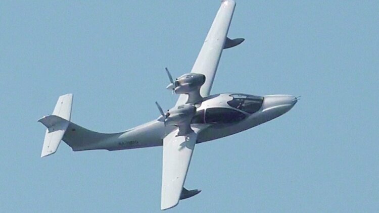 The Selina Aircraft ACK-62 is a twin engined, 6 seat, amphibious aircraft built in Russia by Selina Aircraft. The ACK-62 aircraft was developed by Selina Aircraft (old name is Seregin Aircraft Company) equipped with two engines and retractable landing gear. It’s innovative design and high-tech materials have resulted in excellent aerodynamic and hydrodynamic. The unique design allows this aircraft to carry out take-off and landing on the different types of runways strips and water surfaces, moreover it’s positive climb gradient is maintained even with one running engine. Basic aircraft equipment includes: Integrated complex of electronic display instruments, aircraft supply system is protected by modern electronic cirquit breakers, electrically controlled flaps, ventilation and salon conditioning enabling moisture excess removal, auxiliary power of2kW.
 -
No further off topic posts or I will lock the thread.
-
What has all this to do with experimental and one off aircraft. I started this topic as an adjunct to the aircraft profiles to let you see unique aircraft that did not warrant a full profile. Take your other discussion somewhere else.
-
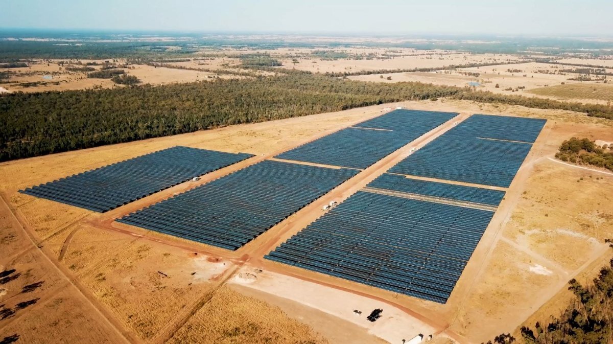
Possibly through solar farms like this one, with approximately 61,000 solar panels covering 73 hectares. However, this topic is for aircraft which were experimental, one off's which never made it into mass production. There is a topic on Social Australia for electric vehicles.

-
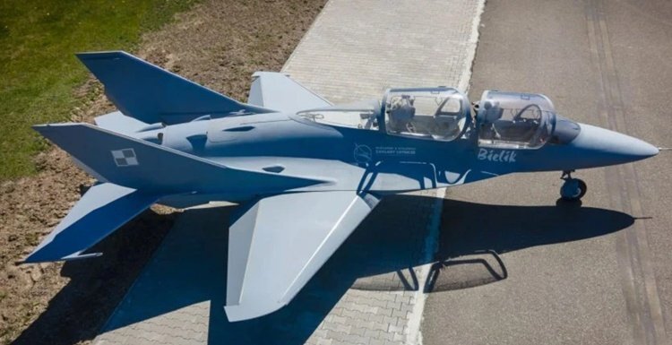
Wingspan: 6.60 m (21 ft 8 in) Height: 2.50 m (8 ft 2 in) Wing area: 11.90 m2 (128.1 sq ft) Aspect ratio: 3.7 Empty weight: 1,700 kg (3,748 lb) Max takeoff weight: 2,500 kg (5,512 lb) Fuel capacity: 850 kg (1,870 lb) Powerplant: 1 × General Electric CJ610-6 turbojet, 13.5 kN (3,000 lbf) thrust prototype; production aircraft 12.75 to 17.65 kN (2,870 to 3,970 lbf) turbojet / turbofan Performance Maximum speed: 1,100 km/h (680 mph, 590 kn) Maximum speed: Mach 0.9 Stall speed: 165 km/h (103 mph, 89 kn) A bit heavy, and stall speed is a tad high.
-
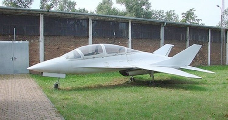
The Margański & Mysłowski EM-10 Bielik (English: white-tailed eagle) is a low-cost Polish military training aircraft prototype, built by Margański & Mysłowski Zakłady Lotnicze, and first flown on 4 June 2003. The single-engine aircraft has a composite (mostly carbon fibre) fuselage with a light-alloy aft section, and the pressurized cockpit is fitted with ejection seats.
-
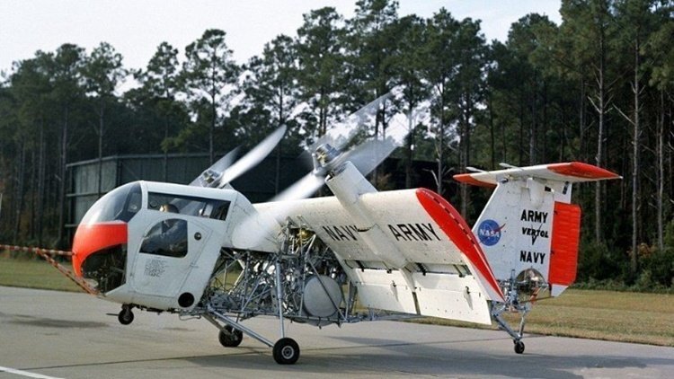
The Vertol VZ-2 (or Model 76) is a research aircraft built in the United States in 1957 to investigate the tiltwing approach to vertical take-off and landing. The aircraft had a fuselage of tubular framework (originally uncovered) and accommodation for its pilot in a helicopter-like bubble canopy. The T-tail incorporated small ducted fans to act as thrusters for greater control at low speeds. Ground tests began in April 1957 and on 13 August, the VZ-2 took off for the first time in hover mode only. On 23 July 1958, the aircraft made its first full transition from vertical flight to horizontal flight. By the time the test program ended in 1965, the VZ-2 had made some 450 flights, including 34 full transitions. The aircraft has been preserved by the National Air and Space Museum in storage at the Paul E. Garber Preservation, Restoration, and Storage Facility. Only the one prototype was produced.
-
MSN WWW.MSN.COM Some interesting video to start with, but the flying aircraft carrier follows.
-
- 2
-
-
The Agusta A.106 was a single-seat light helicopter designed to provide an anti-submarine warfare (ASW) platform for the Impavido-class destroyers of the Italian Navy. The aircraft was provided with a sophisticated electronics suite by Ferranti for autostabilisation and contact identification. Two torpedoes could be slung under the fuselage. The tail and two-bladed main rotor could be folded for shipboard stowage, and the skid undercarriage had fittings for flotation bags. Two prototypes were built, the first flying in November 1965. A pre-production batch of 5 was cancelled by the Navy in 1973.
-
01.jpg.becc478e1b001e67909fc293a039d90d.jpg) The Focke-Achgelis Fa 223 Drache (English: Dragon) was a helicopter developed by Germany during World War II. A single 750-kilowatt (1,010 hp) Bramo 323 radial engine powered two three-bladed 11.9-metre (39 ft) rotors mounted on twin booms on either side of the 12.2-metre-long (40 ft) cylindrical fuselage. Although the Fa 223 is noted for being the first helicopter to attain production status, production of the helicopter was hampered by Allied bombing of the factory, and only 20 were built. The Fa 223 could cruise at 175 kilometres per hour (109 mph) with a top speed of 182 km/h (113 mph), and climb to an altitude of 7,100 m (23,300 ft). The Drache could transport cargo loads of over 1,000 kg (2,200 lb) at cruising speeds of 121 km/h (75 mph) and altitudes approaching 2,440 m (8,010 ft). Henrich Focke had been removed by the Nazi regime from the company he had co-founded in 1936. Though the ostensible reason was that he was "politically unreliable", the RLM decision to phase Focke-Wulf into the production program of the almost-ready Messerschmitt Bf 109 necessitated an influx of capital to fund the immediate expansion of the company's production capabilities. Focke-Wulf was reorganized into a limited company (G.m.b.H.) in June 1936. After Focke-Wulf formally signed a contract to produce the Bf 109C in November 1937, the American company International Telephone & Telegraph (ITT), through its German subsidiary C. Lorenz, bought a 28 percent share of Focke-Wulf in 1938, making it the controlling interest. However, the Air Ministry was so impressed by the Focke-Wulf Fw 61 helicopter that it suggested Focke establish a new company dedicated to helicopter development and issued him with a requirement for an improved design capable of carrying a 700 kg (1,500 lb) payload. Focke established the Focke-Achgelis company at Hoykenkamp on 27 April 1937 in partnership with pilot Gerd Achgelis, and began development work at Delmenhorst in 1938. They first produced an enlarged, six-occupant version of the Fw 61, designated Fa 226 Hornisse (Hornet), while contracting out development of the engine, transmission, and rotor hub to BMW's Berlin works. The Fa 226 was the world's first transport helicopter and was ordered by Lufthansa in 1938. The Fa 226 attracted the attention of the Air Ministry, who redesignated it Fa 223 in 1939 before the first prototype flew.[8] The Navy was also interested in the Hornisse and briefly considered it as a replacement for their Schnellboote. In September 1939 the first prototype, the V1, left the Delmenhorst factory. Now nicknamed Drache ("Dragon") it had a twin-rotor layout similar to the Fw 61, but had a fully enclosed cabin and load bay, with the single Bramo engine mounted in the middle of the tubular-steel body. Initial hovering tests showed problems and the V1 was not to fly until 1940. The engine initially specified, a BMW Bramo 323D proved too fragile when run at high speed for any length of time, and was replaced with a more robust 1,000 hp Bramo 323Q3 in the later prototypes to improve reliability and lifting capability. The biggest problem, however, was the severe vibration caused by unbalanced driveshafts when the rotors moved out of phase, and this could only be fixed by greater attention to detail on the part of BMW. For more details of development, operational history and variants, click here.
The Focke-Achgelis Fa 223 Drache (English: Dragon) was a helicopter developed by Germany during World War II. A single 750-kilowatt (1,010 hp) Bramo 323 radial engine powered two three-bladed 11.9-metre (39 ft) rotors mounted on twin booms on either side of the 12.2-metre-long (40 ft) cylindrical fuselage. Although the Fa 223 is noted for being the first helicopter to attain production status, production of the helicopter was hampered by Allied bombing of the factory, and only 20 were built. The Fa 223 could cruise at 175 kilometres per hour (109 mph) with a top speed of 182 km/h (113 mph), and climb to an altitude of 7,100 m (23,300 ft). The Drache could transport cargo loads of over 1,000 kg (2,200 lb) at cruising speeds of 121 km/h (75 mph) and altitudes approaching 2,440 m (8,010 ft). Henrich Focke had been removed by the Nazi regime from the company he had co-founded in 1936. Though the ostensible reason was that he was "politically unreliable", the RLM decision to phase Focke-Wulf into the production program of the almost-ready Messerschmitt Bf 109 necessitated an influx of capital to fund the immediate expansion of the company's production capabilities. Focke-Wulf was reorganized into a limited company (G.m.b.H.) in June 1936. After Focke-Wulf formally signed a contract to produce the Bf 109C in November 1937, the American company International Telephone & Telegraph (ITT), through its German subsidiary C. Lorenz, bought a 28 percent share of Focke-Wulf in 1938, making it the controlling interest. However, the Air Ministry was so impressed by the Focke-Wulf Fw 61 helicopter that it suggested Focke establish a new company dedicated to helicopter development and issued him with a requirement for an improved design capable of carrying a 700 kg (1,500 lb) payload. Focke established the Focke-Achgelis company at Hoykenkamp on 27 April 1937 in partnership with pilot Gerd Achgelis, and began development work at Delmenhorst in 1938. They first produced an enlarged, six-occupant version of the Fw 61, designated Fa 226 Hornisse (Hornet), while contracting out development of the engine, transmission, and rotor hub to BMW's Berlin works. The Fa 226 was the world's first transport helicopter and was ordered by Lufthansa in 1938. The Fa 226 attracted the attention of the Air Ministry, who redesignated it Fa 223 in 1939 before the first prototype flew.[8] The Navy was also interested in the Hornisse and briefly considered it as a replacement for their Schnellboote. In September 1939 the first prototype, the V1, left the Delmenhorst factory. Now nicknamed Drache ("Dragon") it had a twin-rotor layout similar to the Fw 61, but had a fully enclosed cabin and load bay, with the single Bramo engine mounted in the middle of the tubular-steel body. Initial hovering tests showed problems and the V1 was not to fly until 1940. The engine initially specified, a BMW Bramo 323D proved too fragile when run at high speed for any length of time, and was replaced with a more robust 1,000 hp Bramo 323Q3 in the later prototypes to improve reliability and lifting capability. The biggest problem, however, was the severe vibration caused by unbalanced driveshafts when the rotors moved out of phase, and this could only be fixed by greater attention to detail on the part of BMW. For more details of development, operational history and variants, click here. -
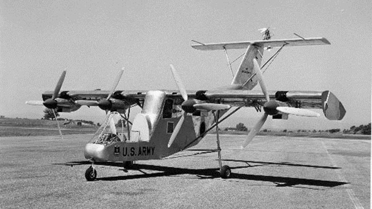
The Fairchild VZ-5 (or Model M-224-1) was an experimental VTOL aircraft built in the 1950s. The VZ-5 was designed by Fairchild Aircraft for research use by the United States Army. The VZ-5 prototype was built as part of a series of experimental aircraft designed to study various designs for VTOL aircraft and solve problems related to vertical and short takeoff. The VZ-5 was an all-metal high-wing monoplane with a fixed tricycle undercarriage. The fuselage had an open cockpit for one pilot and a rear-mounted high-tailplane. The unusual aspect of the aircraft was that it had one General Electric turboshaft in the rear fuselage driving four propellers, two each mounted in nacelles on the leading edge of each wing. It also had two small four-bladed tail-rotors mounted above the tailplane for control. The wing had conventional trailing edge flaps and ailerons but it also had a section of the wing that could be deflected to act as a full-span flap. For a vertical takeoff two-thirds of the wing chord acted as a flap in the slipstream of the four propellers. The VZ-5 was first flown tethered on 18 November 1959 but only had limited testing before the project was abandoned.
-
 The Vickers Type 56 Victoria was a British biplane freighter and troop transport aircraft used by the Royal Air Force. The Victoria flew for the first time in 1922 and was selected for production over the Armstrong Whitworth Awana. The Victoria was a twin-engined biplane transport with a conventional landing gear with a tailskid. The design mated a similar fuselage of the earlier Vernon transport with the wing of the Virginia bomber, which was developed in parallel. It was also powered by two Napier Lion engines. The enclosed cabin had room for 24 troops on collapsible canvas seats arranged along the sides of the fuselage. In April 1921 two prototypes were ordered by the Air Ministry to Specification 5/20. The first prototype, allocated serial number J6860, was built as a Type 56 and designated as Victoria I, the second J6861 was built as a Type 81 Victoria II. The Type 56 had two 450 hp (340 kW) Napier Lion engines with large frontal radiators and were fitted directly onto the lower mainplanes, the fuel tanks were placed under the inboard section of the bottom mainplane. The prototype J6860 first flew from Brooklands, Surrey on 22 August 1922. The Type 81 flew in January 1923, and initially differed only in having the fuel tanks under the top mainplane.[5] It was later modified by replacing the flat sided engine cowling with more streamlined nacelles with the radiators between the undercarriage legs, as fitted in the Virginia II bomber. In March 1925, it was decided to place an order for 15 production aircraft. By this time, the Virginia design had evolved to incorporate swept-back wings, and the production Victoria IIIs incorporated this change. Another improvement first introduced in the Virginia was the introduction of metal structures instead of the all-wooden airframes of the early aircraft, with an order being placed for a prototype Victoria with a metal structure (serial number J9250) in September 1927, this being delivered in October 1928. The metal airframe proved much more suitable for the hot and humid areas where the Victoria served, with Victoria IV and Vs with metal structures produced by conversion and new production respectively. The final version was the Mark VI, which substituted modern, more powerful Bristol Pegasus radial engines for the Napier Lions. The Vickers Valentia was a further improved version with a stronger structure, capable of operating at higher weights. 97 Victorias were built, many of which were later converted into Valentias. Variants Type 56 Victoria Mk I The first prototype. Powered by two 450 hp (340 kW) Napier Lion IAX W12 engines. Type 81 Victoria Mk II The second prototype. Type 117 Victoria Mk III The first production version. Military transport aircraft for the RAF. Powered by 450 hp Napier Lion II engines. 46 built. Type 145 Victoria Mk IV Metal wing structure. One prototype powered by Bristol Jupiter radials.[19] Thirteen Lion-engined conversions from earlier marks. Type 169 Victoria Mk V New production aircraft with metal structure, powered by two 570 hp (430 kW) Napier Lion XIB engines. 37 new-built. Type 262 Victoria Mk VI Final production - powered by 660 hp (490 kW) Bristol Pegasus IIL3 engines instead of Lions. 11 new-build, 23 by conversion.
 -
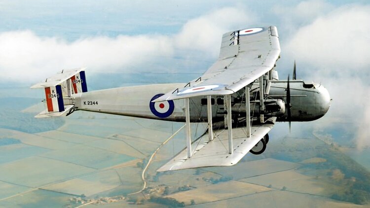
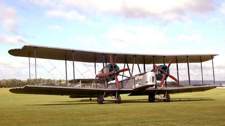 The Vickers Vimy was a British heavy bomber aircraft developed and manufactured by Vickers Limited. Developed during the latter stages of the First World War to equip the Royal Flying Corps (RFC), the Vimy was designed by Rex Pierson, Vickers' chief designer. Only a handful of Vickers Vimy aircraft had entered service by the time the Armistice of 11 November 1918 came into effect, so the type did not serve in active combat operations during the war, but the Vimy became the core of the Royal Air Force (RAF)'s heavy bomber force throughout the 1920s. The Vimy achieved success as both a military and a civil aircraft, the latter using the Vimy Commercial variant. A dedicated transport derivative of the Vimy, the Vickers Vernon, became the first troop-transport aircraft operated by the RAF. During the interwar period the Vimy set several records for long-distance flights, the most celebrated and significant of these being the first non-stop crossing of the Atlantic Ocean, performed by John Alcock and Arthur Brown in June 1919. Other record-breaking flights were made from the United Kingdom to destinations such as South Africa and Australia. The Vimy continued to be operated until the 1930s in military and civil capacities. The Vickers F.B.27 Vimy is an equal-span twin-engine four-bay biplane, with balanced ailerons on both upper and lower wings. The engine nacelles were positioned mid-gap and contained the fuel tanks. It has a biplane empennage with elevators on upper and lower surfaces and twin rudders. The main undercarriage consists of two pairs of wheels, each pair carried on a pair of tubular steel V-struts. There is a tail-skid and an additional skid mounted below the nose of the fuselage to prevent nose-overs. The aircraft was designed to accommodate a three-man crew and a payload of 12 bombs. In addition to the pilot's cockpit, which was positioned just ahead of the wings, there were two positions for gunners, one behind the wings and the other in the nose, each with a pair of Scarff ring-mounted Lewis guns; the rear cockpit mounting was commonly not fitted during the interwar period. Provision for a maximum of four spare drums of ammunition were present in the nose position, while up to six drums could be carried in the rear position. The majority of the Vimy's payload of 250 lb (110 kg) bombs were stowed vertically inside the fuselage between the spars of the lower centre section; a typical load consisted of 12 bombs.[1] In some variants further bombs could be stowed externally for a total of 18 bombs, if the particular engine used provided enough power. For anti-surface warfare in the maritime environment, the Vimy could also be armed with a pair of torpedoes. To improve bombing accuracy, the Vimy was equipped with the High Altitude Drift Mk.1a bombsight. Standard equipment also included two Michelin-built Mk.1 flare carriers. The Vimy was powered by a range of different engines. Owing to engine supply difficulties, the prototype Vimys were tested with a number of different engine types, including Sunbeam Maoris, Salmson 9Zm water-cooled radials, and Fiat A.12bis engines, before production orders were placed for aircraft powered by the 230 hp (170 kW) BHP Puma, 400 hp (300 kW) Fiat, 400 hp (300 kW) Liberty L-12 and the 300 hp (270 kW) Rolls-Royce Eagle VIII engines, with a total of 776 ordered before the end of the First World War. Of these, only aircraft powered by the Eagle engine, known as the Vimy IV, were delivered to the RAF.[5] Due to the number of engine types used there are multiple conflicting official reports on the production numbers of each sub-variant of the Vimy. Design and production of the prototypes was extremely rapid; the detailed design phase of what had become internally designated as the Vickers F.B.27 and the manufacture of the three prototypes was completed within four months. Long-distance flights The most significant of the Vimy's many pioneering flights was the first non-stop crossing of the Atlantic Ocean, made by Alcock and Brown in June 1919. An example was specially constructed for the attempt, with additional fuel tanks to extend its range and a revised undercarriage. Only one such aircraft was built; it is preserved and displayed in the London Science Museum. In 1919, the Australian government offered £10,000 for the first All-Australian crew to fly an aeroplane from England to Australia. Keith Macpherson Smith, Ross Macpherson Smith and mechanics Jim Bennett and Wally Shiers completed the journey from Hounslow Heath Aerodrome to Darwin via Singapore and Batavia on 10 December 1919. Their aircraft G-EAOU is preserved in a purpose-built, climate-controlled museum in the grounds of the airport in Smith's home town Adelaide, Australia; "The trip from Darwin to Sydney took almost twice as long as the flight to Australia." Vickers Vimy Reserve in Northgate, a suburb of Adelaide, is named in honour of the place the plane landed on its return to South Australia in 1920. In 1920 Lieutenant Colonel Pierre van Ryneveld and Major Quintin Brand attempted the first England to South Africa flight. They left Brooklands on 4 February 1920 in Vimy G-UABA, named Silver Queen. They landed safely at Heliopolis, but as they continued the flight to Wadi Halfa they were forced to land due to engine overheating with 80 miles (130 km) still to go. A second Vimy was lent to the pair by the RAF at Heliopolis, and named Silver Queen II. This second aircraft reached Bulawayo in Southern Rhodesia, where it was badly damaged when it failed to take off. Van Ryneveld and Brand then used a South African Air Force Airco DH.9 to continue the journey to Cape Town. The South African government awarded them £5,000 each. Variants F.B.27 Vimy Prototypes; four built, powered by two 200 hp (150 kW) Hispano-Suiza 8 piston engines.. F.B.27A Vimy II Twin-engine heavy bomber aircraft for the RAF, powered by two 300 hp (220 kW) Rolls-Royce Eagle VIII piston engines. Vimy Ambulance Air ambulance version for the RAF.[36] Vimy Commercial Civilian transport version, powered by two 300 hp (220 kW) Rolls-Royce Eagle VIII and later 360 hp (270 kW) Rolls-Royce Eagle IX piston engines. A.N.F. 'Express Les Mureaux' Vimy Commercial No.42 re-engined with 2x 370 hp (280 kW) Lorraine 12Da V-12 engines by ANF Les Mureaux. For more details of background, production, operational history and operators, click here. This aircraft is on display at Adelaide Airport.
 -
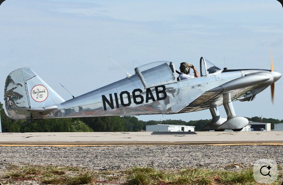
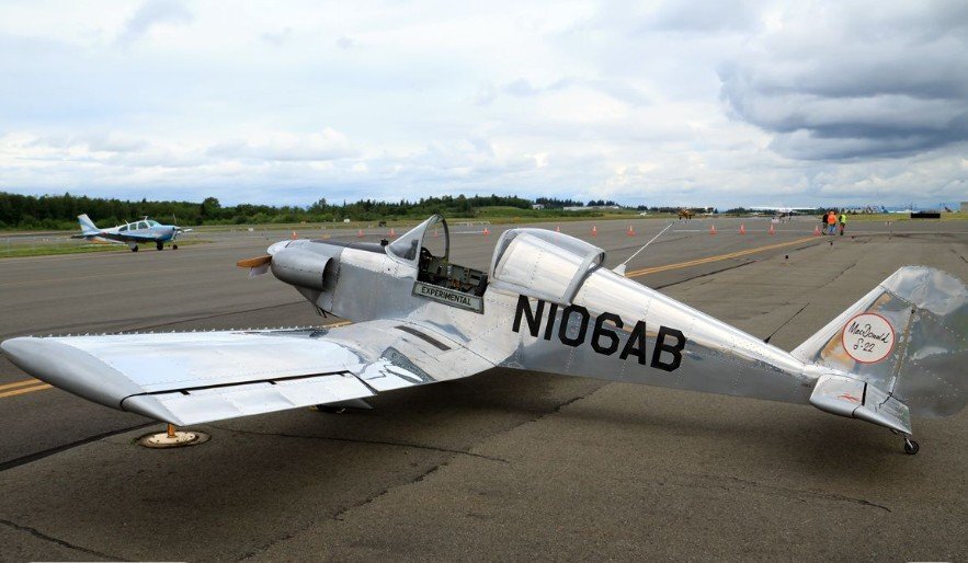
The MacDonald S-20 is a single-seat sport aircraft that was designed in the United States in the early 1970s and marketed for home building. The aircraft is a conventional, low-wing cantilever monoplane with fixed tailwheel undercarriage and an open cockpit. Construction is of metal throughout, with a forward fuselage of welded steel tube construction, with the rear fuselage built up of aluminium bulkheads and longerons. The wings and tail are also of aluminium construction, and the entire aircraft is skinned in the same material. Pop rivets are used extensively to simplify construction. The S-20 designation was applied to the prototype (registration N106AB), while aircraft built from the plans were designated S-21. In 2009 and 2010 changes were made to the original design to add a cockpit canopy, engine cowling and electrical system, including an avionics bus and starter motor. Aircraft with these changes are designated S-22.
-
Here is a link to a large collection of photos of Aussie aircraft (and visiting international aircraft). Recent additions to the photostream are aerobatics and formation photos from the Great Eastern Fly-in 2014 but only recently uploaded. Click on the image to access the site.
-
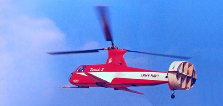 Not to be confused with Piasecki H-16 Transporter. The Piasecki 16H was a series of compound helicopters produced in the 1960s. The first version of the Pathfinder, the -1 version, first flew in 1962. The similar but larger Pathfinder II, the 16H-1A, was completed in 1965. Variants Model 16H-1 Pathfinder one PWC PT6B-2 with one 405 shp turboshaft engine Model 16H-1A Pathfinder II Specifications below larger version with one 1,250 shp (930 kW) T58-GE-8 Model 16H-1C Pathfinder III proposed conversion of the 16H-1A with one 1,500 shp (1,100 kW) T58-GE-5 Model 16H-3J nine-seat development, not built.
 -
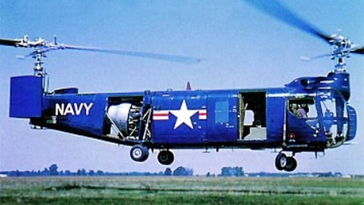 The Bell HSL (Model 61) was an American 1950s anti-submarine warfare (ASW) helicopter built by Bell Helicopter for the US Navy. The prototype first flew in 1953, but the type became obsolete during development and was found unsatisfactory upon entering service in 1957, resulting in the cancellation of the production contract; many of the 50 production aircraft were delivered directly into storage. The last HSL was retired in 1960. It was the only tandem rotor type designed by Bell. The prototype Bell Model 61 first flew on 3 March 1953; it had been designed to meet a United States Navy requirement for an anti-submarine warfare helicopter. In June 1950, the Model 61 was announced as the winner of the competition, and three XHSL-1 evaluation aircraft were ordered. The Model 61 had a rectangular-section fuselage structure and four-leg, six-wheel landing gear.[citation needed] It was powered by a Pratt & Whitney R-2800 radial engine mounted in the aft fuselage. Crew included two pilots and two sonar operators. The main rotors were at either end of the fuselage tube, linked by a transmission. The front rotor shaft was slightly ahead of pilots in the front cockpit. Because of the urgency of the requirement, low-rate production was ordered almost immediately after Bell received a contract for three XHSL-1s. The Navy eventually contracted for at least 160 production aircraft, including 18 intended for the British Royal Navy. Bureau Numbers were assigned for a total of 234. Because of development problems that resulted in poor schedule performance to the contract, only 50 were built. Although all were delivered, after service test and acceptance only a handful were used, for the development of airborne mine sweeping. The rest were delivered directly into storage and were subsequently struck off. Variants XHSL-1 two experimental flight test and one static test article HSL-1 production version, 50 built. Bell Model 61 Company designation for the HSL Bell D-116 A proposed civil variant of the Model 61, not proceeded with. Bell D-216 A proposed variant of the HSL, not proceeded with. Bell D-238 A proposed variant of the HSL, not proceeded with.
 -
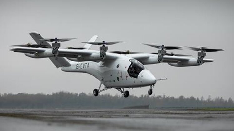 Vertical Aerospace Ltd. is an aerospace manufacturer based in Bristol, England. It designs and builds zero emission, electric vertical take-off and landing (eVTOL) electrically powered aircraft. The company was founded in 2016 by Stephen Fitzpatrick, an ex-Formula One team owner, and founder and CEO of OVO Energy. In June 2018, the company flew its first prototype aircraft — an electrically powered quadcopter that weighed 750 kg (1,650 lb), named VA-X1. In 2019, the company became Honeywell's first eVTOL customer, buying their fly-by-wire aircraft control systems for a future Vertical Aerospace aircraft, the VA-X4. in February 2021, the company announced it was partnering with Solvay S.A. for the development of the composite structure of its vehicle. In March, the company announced it was partnering with Rolls-Royce for the development of its electrical power system. In the period between 2020 and 2022, under the leadership of Chief Engineer, Tim Williams, Vertical Aerospace successfully designed, built, and flew the VX-4 prototype aircraft. This achievement marked a historic moment in the aerospace industry, as it was the first of its kind – a new technology, electric-powered aircraft – to be created in the United Kingdom in living memory. The aircraft accomplished its first takeoff and landing while tethered to the ground in September. In 2023, the VX4 successfully completed an unmanned test flight at Kemble Airport, Cotswold UK. The aircraft demonstrated its capabilities by lifting off, hovering, flying, and landing solely through the thrust generated by Vertical's proprietary battery packs. The prototype was damaged during uncrewed flight testing on 9 August 2023 at Cotswold Airport. The company attributed the accident to a fault with the propeller, but said it was an older design that had since been replaced. In 2024 the second full-scale prototype of the VX4 was revealed. It was claimed to use a proprietary battery and a powertrain system with 20% greater power. The prototype also included redesigned carbon fiber propellers to lower noise and improve performance. In January 2025, piloted hover flight tests were successfully carried out. The next testing stage is low-speed manoeuvres. Vertical Aerospace says that the VX4 is a piloted, zero emissions electric vertical take off and landing (eVTOL) vehicle with an expected range of over 100 miles (160.9 km), capacity for 4 passengers and a pilot, and runs quieter than a helicopter. The proposed aircraft is intended to operate in and out of cities and other confined locations. It would rely on its fixed wing for lift during most of a flight. This shift follows the eVTOL industry, which is shifting towards wing-borne lift + cruise and vectored thrust concepts, due to the efficiency gains wing-borne lift offers while cruising. It features eight propellers mounted to the wing. The four front-mounted propellers shift from providing lift in take-off mode to providing forward thrust while cruising. The rear motors operate only during take-off and landing. No specifications are available at this time.