red750
-
Posts
8,237 -
Joined
-
Last visited
-
Days Won
78
Content Type
Profiles
Forums
Gallery
Downloads
Blogs
Events
Store
Aircraft
Resources
Tutorials
Articles
Classifieds
Movies
Books
Community Map
Quizzes
Videos Directory
Everything posted by red750
-
 Renowned aerobatic pilot Rob Holland tragically lost his life on Thursday, April 24, 2025, when his experimental aircraft crashed at Langley Air Force Base in Hampton, Virginia. The accident involved an MX Aircraft MXS, a high-performance, single-seat plane built by an Australian company specializing in aerobatic and racing aircraft. https://dailytopis.com/legendary-aerobatic-pilot-rob-holland-dies-in-crash-at-langley-air-force-base/
 -
Ignored Warnings, Fatal Decisions, and Years of Silence — The Ricky Nelson Mystery Is Finally Solved and It Isn’t Good MS2.XYNO.ONLINE In a shocking conclusion that overturns decades of speculation, the mystery surrounding the tragic death of rock and roll legend Ricky...
-
https://www.msn.com/en-au/news/other/ntsb-reveals-causes-of-mid-air-plane-crash-that-killed-67-in-dc/ar-AA1V72Wn?ocid=winp2fptaskbar&cvid=6979f51399ff4212ba6522dab418ada1&ei=42
-
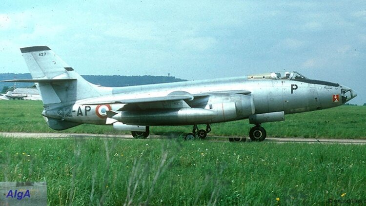 The Sud-Ouest Aviation (SNCASO) S.O. 4050 Vautour (French for vulture) is a French jet-powered multirole aircraft. The Vautour served as a bomber, ground attack, reconnaissance and interceptor aircraft. Developed and manufactured by aircraft company Sud Aviation, the Vautour was operated by France's Armée de l'Air, having been originally designed in response to a requirement for a jet aircraft for bombing, low-level attack and all-weather interception. The Vautour was used in the Force de frappe under the Commandement des forces aériennes stratégiques; each aircraft was suitable for the carriage of a nuclear weapon. The shortcomings of the type as a bomber, such as its lack of radar or other advanced navigation/attack systems, led to the type being replaced by the more capable Dassault Mirage IV. The Vautour never saw combat with the French Air Force. The only other user was the Israeli Air Force (IAF), for which the Vautour undertook various mission and roles, including combat. Vautours were used during the wars between Israel and its neighbors, including the Six-Day War and the War of Attrition. Only one air-to-air kill was recorded by a Vautour; the type was used more for bombing and ground strafing and was reportedly considered by Israel to be comparable to the Soviet-built Ilyushin Il-28 medium bombers used by its regional adversaries. During the early 1970s, the Israeli Vautours were replaced by Douglas A-4 Skyhawks. The Sud Aviation Vautour was a jet-propelled mid-sized combat aircraft, typically employed as a bomber and attack aircraft, as well as having some usage as an interceptor.[1] In terms of its basic configuration, it had a shoulder-wing monoplane configuration, furnished with a 35° swept wing and a "flying" tail. Power was provided by a pair of SNECMA Atar 101 turbojet engines, which were carried in pods located underneath the wings.[10] The Vautour was equipped with a bicycle-type landing gear configuration in which the main units were located upon the underside of the fore and aft fuselage, these were augmented by smaller stabilizing gear set into bottom of the engine pods. The internal space of the central fuselage was largely dedicated to a large 5 m (16 ft) weapons bay, along with substantial internal fuel tankage. The Vautour IIB bomber lacked any sort of radar arrangement or many of the contemporary navigational aids and attack systems that were installed upon several aircraft performing the same role during this era. Aiming of the armaments was performed by a bombardier, who would principally perform his bomb-aiming function using a Second World War-vintage American-built Norden bombsight. The navigator/bombardier position was within the nose section, which was glazed to provide external visibility.[3] Both the Vautour IIB and IIA models were restricted to performing missions only under clear-weather operations during daylight. The Vautour IIN interceptor model was not as restrictive, having some capacity to conduct both nighttime and adverse weather operations, having been furnished with a radar system. During its service in Israel, where the weather of the local climate was generally favorable and daylight missions commonplace, the Vautour's lack of advanced targeting and navigation equipment was found to be not a crippling limitation. However, when operated in Europe, these restrictions were considered to be a major disadvantage. As a result, the French AdA never deployed their single-seat Vautour IIA fleet in a frontline capacity; the majority of its IIB bombers were quickly converted to the improved Vautour IIBR standard, which was used to perform photo reconnaissance missions instead. The Vautour was capable of being equipped with various armaments. In Israeli service, it was typically armed with a pair of 30 mm cannons, as well as up to four removable underwing rocket pods, containing up to 19 air-to-ground rockets each; up to 3,000 kg (6,600 lb) of bombs or alternatively a maximum of 232 68 mm rockets could be accommodated internally in the bomb bay. 4,000 kg (8,800 lb) of bombs could also be mounted externally.[6] The Vautour IIB bomber could be used to carry nuclear weapons in addition to its conventional arsenal. The internal bomb bay of an aircraft could contain either one AN-11 or one AN-22 nuclear bomb; in AdA service, the primary carrier of nuclear weapons would quickly be changed to the newer and more capable Dassault Mirage IV, which supplemented and eventually replace the Vautour IIB bomber. For operational history and variants, click here.
 -
Here is video of the aircraft taking off from Oshkosh, and after it crashed on landing, but not the crash itself. Spirit Engineering SE-1 crash.mp4
-
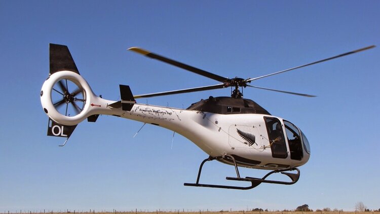 The Composite Helicopters International KC 518 Adventourer is a composite fuselage, 5-6 place turbine kit helicopter. The KC 518 is a composite fuselage helicopter kit for amateur construction. The airframe uses a carbon fiber and kevlar composite fuselage with a shrouded tail rotor. An auxiliary fuel system can be installed. Variants Other versions with the same fuselage are KC630 with Rolls-Royce RR300 engine in 2017 (priced at US$970,000), KC640 with the RR250 in 2018, and KC650 with the Honeywell LTS101, expected to be certified by 2019. The rights to the KC630 were acquired by Innova Helicopters in 2017.
 -
Light aircraft crash at Heck Field 27/01/26
red750 replied to red750's topic in Aircraft Incidents and Accidents
Midday news report. Both male occupants confirmed deceased. Fire spreading fast in dry conditions with a strong wind. Most stupid report: They haven't located a black box. -
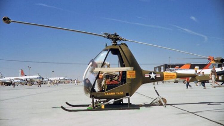 The Hiller YH-32 Hornet (company designation HJ-1) is an American ultralight helicopter built by Hiller Aircraft in the early 1950s. It was a small and unique design because it was powered by two Hiller 8RJ2B ramjet engines mounted on the rotor blade tips which weigh 13 lb (5.9 kg) each and deliver an equivalent of 45 hp (34 kW) for a total of 90 hp (67 kW). Versions of the HJ-1 Hornet were built for the United States Army and the United States Navy in the early 1950s. The Hiller Museum identifies the YH-32A, named the Sally Rand, as the first helicopter gunship. The Hiller HOE-1 became the first production ramjet helicopter, and the Army and Navy flew a small number of these aircraft for a short time to test and evaluate the technology. The Hiller HJ-1 Hornet was an early attempt to build a jet-powered helicopter using ramjets, with work beginning in 1948. Before that there had been experiments with the XH-26 Jet Jeep tip rotor pulse jets.The HJ-1 ramjet tipped rotor propels the rotor and the aircraft. Unlike a conventional helicopter, this mechanically simple design avoids the need for a tail rotor. Unfortunately, the tip speeds on helicopter rotor blades are subsonic, and ramjets are inefficient at subsonic speeds due to low compression ratio of the inlets. Therefore, the Hornet suffered from high fuel consumption and poor range. Also, the vehicle suffered from low translational speeds, and the ramjet tips were extremely noisy. In the event of power loss, autorotation was found to be difficult due to the drag from the ramjet nacelles. The vehicle exhibited powerful lifting capacity, and there was some hope for military uses, but the high noise, poor range, and high night-time visibility of the ramjet flames failed to attract sales. The first Hiller Hornets were not ready for delivery until late 1954, due to Hiller certificating the aircraft to Civil Aviation Authority standards rather than military specifications. Variants HJ-1 Company designation, one prototype. YH-32 United States Army, Similar to HJ-1 with two small v-shaped stabilizers, 14 built (2 prototypes and 12 production aircraft). YH-32A Two YH-32s modified for trials as an armed helicopter. XHOE-1 Three HJ-1s for evaluation by the United States Navy in 1951. Number built 18.
 -
A light aircraft with two persons on board crashed at Heck Field around 6:30 am today. Details are scarce, with authorities unsure if it was arriving or departing. Fears are that both occupants may be deceased.
-
air moments crosswind.mp4
-
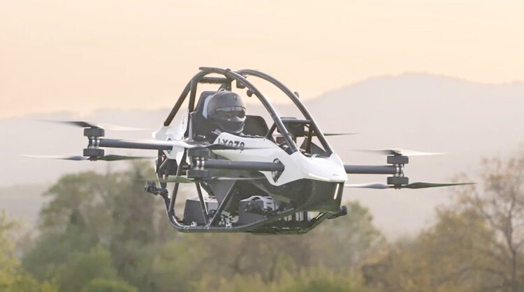 The Jetson ONE is a type of personal ultralight known as an eVTOL. It is a 102-horsepower battery-operated ultralight with eight electric motors. A Swedish startup company, Jetson, produces the personal ultralight, which is manufactured and tested in Arezzo, Italy. To fly the single-seat ultralight, the operator does not need a pilot licence or special training in the US. It is equipped with a parachute. Late 2017, Tomasz Patan built a working "proof of concept" of an electric VTOL personal flying vehicle with the goal of "making everyone a pilot." In 2018, Patan designed a personal flying car. The design was improved, and in 2021, Patan invented a new model called the Jetson ONE eVTOL. In 2022, the company offered the Jetson Ones for US$92,000 each. In 2022, the company began manufacturing the Jetson One in Poland. In 2022, the company moved production and testing of the Jetson ONE from Poland to a facility in Arezzo, Italy. The company's CEO is Stephan D'haene, and he announced that the company obtained approval from the Italian Civil Aviation Authority (ENAC) to fly the aircraft in Italy's uncontrolled airspace. In 2023, the company announced that it had raised US$15 million to fund the project. They planned to begin delivering the next Jetson ONEs in 2024. The vehicle has a charger which can recharge in one hour at 230/240 V or two hours with 120 V power. Batteries may be removed and changed to avoid waiting for charging. The person piloting the ultralight must be less than 210 lb (95 kg). The ultralight is capable of flight even if one of the engines fails. It is equipped with lidar sensors to avoid obstacles. There is a rapid-deploying ballistic parachute, and the ultralight has a mode which allows the craft to hover without operating the controls. Joysticks control it, and it has a throttle lever to adjust power. The left controller operates the ultralight's altitude, and the right controls the direction.
 -
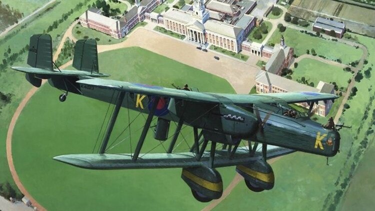 The Handley Page Heyford was a twin-engine biplane bomber designed and produced by the British aircraft manufacturer Handley Page. It holds the distinction of being the last biplane heavy bomber to be operated by the Royal Air Force (RAF). The Heyford was developed in response to Specification B.19/27 for a new heavy night bomber. Much of the design can be attributed to the work of George Volkert, Handley Page's lead designer. Unlike the company's preceding aircraft, the Heyford comprised metal construction instead of wood; it also had an unorthodox arrangement wherein the fuselage was joined to the upper wing rather than the lower one, which gave the aircraft a relatively nose-high orientation while on the ground. Considerable revision of the proposal occurred even after its submission, which was recognised as the Air Ministry's preferred option. A sole prototype, designated Handley Page HP.38, was produced, performing its maiden flight on 12 June 1930 and commencing service trials shortly thereafter. During November 1933, the first Heyfords entered service, being initially flown by No. 99 Squadron at RAF Upper Heyford; before the end of 1936, Bomber Command had a total of nine operational squadrons equipped with the Heyford. Despite forming a considerable portion of the RAF's bomber fleet during the mid-1930s, the Heyford had a relatively short service life as it was rapidly eclipsed by a new generation of monoplane bombers, such as the Armstrong Whitworth Whitley and the Vickers Wellington. The replacement of the type had commenced during 1937 as more capable bombers were introduced during a major rearmament push for the RAF; the Heyford was formally declared obsolete in July 1939, barely two months prior to the outbreak of the Second World War. Despite this, the type continued to be used in secondary roles, being used as glider tugs, experimental aircraft, and trainers, into the 1940s. The Handley Page Heyford was a twin-engine biplane bomber designed for nighttime operations. It featured a relatively novel configuration in which the fuselage was attached to the upper wing – somewhat resembling the 1914-designed German Gotha G.I. This arrangement provided a favourable field of fire for its defensive weapons, which were positioned on the nose and dorsal sections, along with the ventral retractable "dustbin" turret, each of which were armed with a single .303 in (7.7 mm) Lewis light machine gun. The wings of the Heyford were equal in both span and dihedral. The lower wing featured a thickened center section to accommodate the aircraft's single bomb bay. Automated wing tip slots improved the take-off performance considerably. Propulsion consisted of a pair of Rolls-Royce Kestrel engines, which each drove a set of fixed-pitch propellers. The Heyford featured a mixed construction; its wings were covered by fabric while the structure comprised a twin-bay metal frame, while the fuselage consisted of an aluminium monocoque forward section with a fabric-covered frame to the rear. It was operated by a crew of four, typically consisting of a pilot, a bomb aimer/navigator/gunner, a radio operator and a dorsal/ventral gunner. Open positions were provided for the pilot and both the nose and dorsal gunners. The Heyford was furnished with a fixed undercarriage that consisted of large, spat-covered wheels that were mounted at the leading edge of the lower wing. This arrangement enabled ground crews to safely attach bombs even as the engines were still running, but also had the consequence of positioning the pilot roughly 17 ft (5 m) above the ground. Another benefit of this nose-high angle was a relatively short and speedy take-off run. Variants H.P.38 Single prototype powered by two Rolls-Royce F.XIV engines and flown in June 1930. H.P.50 Heyford I Powered by 575 hp (429 kW) Rolls-Royce Kestrel III engines: 15 built, serial numbers K3489-K3902 (last aircraft built as Mk.II prototype). H.P.50 Heyford IA Engine support changes, power-driven generator, four-blade propellers: 23 built, serial numbers K4021-K4043. H.P.50 Heyford II Powered by 640 hp (480 kW) Kestrel IV engines: 16 built, serial numbers K4863-K4878. H.P.50 Heyford III Supercharged 695 hp (518 kW) Kestrel VI engines: 70 built in two batches, serial numbers K5180-K5199 and K6857-K6906. For a total of 125 (including the prototype, J9130)
 -
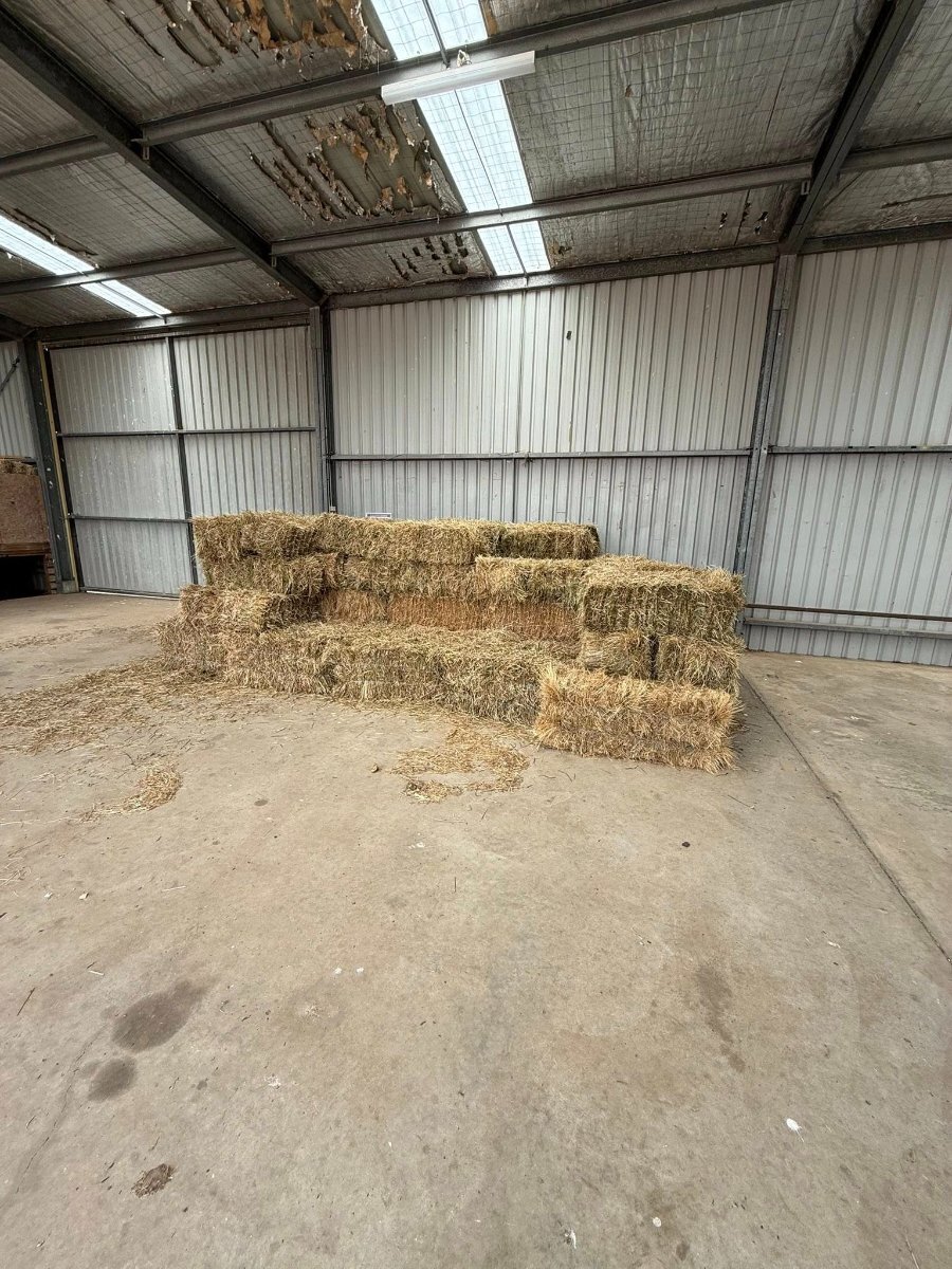
Tell them it's a hayshed

-
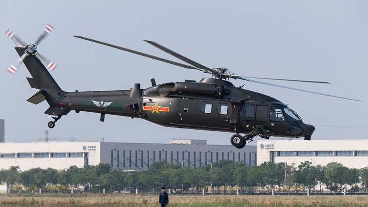 The Harbin Z-20 (Chinese: 直-20) is a series of Chinese medium-lift utility helicopter produced by the Harbin Aircraft Industry Group (HAIG). It was first flown on 23 December 2013 and has a maximum takeoff weight in the range of 10 tonnes (22,000 lb). The Z-20 can operate from locations above 4,000 m (13,000 ft) in altitude as well as from the Liaoning aircraft carrier. It is regarded to be comparable in performance to the US-made Sikorsky UH-60 Black Hawk helicopter, of which the civilian Sikorsky S-70C-2 variant has been used by the People's Liberation Army since 1984. The People's Liberation Army Air Force (PLAAF) has had a requirement for a high-altitude medium utility helicopter that can operate in the mountainous regions in China since the 1980s. In 1984, the PLAAF acquired 24 Sikorsky S-70C-2s with enhanced General Electric T700-701A engines from the US government. China was unable to purchase more Sikorsky aircraft following the fallout from the 1989 Tiananmen Square protests that resulted in an EU and US arms embargo. This led to the development of an indigenous so-called "10-tonne helicopter project" that started in 2006, and the Z-20 made its first flight on 23 December 2013. Helicopter production in China received a massive boost after the 2008 Sichuan earthquakes highlighted the value of helicopters in humanitarian missions. In addition to the PLAAF, the Z-20 will likely be used by other services in the People's Liberation Army. It could fill the role of a multi-role naval helicopter for the People's Liberation Army Navy (PLAN) that is small enough to be interoperable across all PLAN vessels while still have a full suite of anti-submarine warfare (ASW) capabilities installed. The Z-20 has been tested carrying missiles on wing pylons. A stealth Z-20 variant has been indicated under development since 2015. One analyst said China could produce the stealth variant relatively easily because of their access to a modified MH-60 Black Hawk tail section, recovered by Pakistani security forces after a crash during the Bin Laden raid. In May 2021, the concept model of the stealthy Z-20 variant was public revealed. The model displayed a trapezoidal airframe, a shrouded main rotor hub, and an upper-facing ventilation system located on an enlarged tail boom. Variants Z-20 Base transport variant for PLA Army. Z-20T Assault Variant Armed assault variant featuring stub wings with two hardpoints each for weapons and targeting sensors, used by PLA Army. Z-20S Search and rescue (SAR) used by PLA Army. Equipped with FLIR, a searchlight under the fuselage, a hoist above the cabin door, a crash position indicator (CPI) underneath the tail boom, new ECM antennas above the LWR, and essential medical equipment inside the cabin. Z-20K PLAAF airborne corps variant. Z-20KA PLAAF airborne corps air assault variant, featuring additional hardpoints for weapons and EO sensors. Z-20KS PLAAF airborne corps combat search and rescue variant. Z-20J Naval utility/transport variant. Z-20F Naval ASW variant. Equipped with surface radar under nose, pylon for torpedoes, dipping sonar underbelly and bubble window for observation. Z-20 PAP variant for People's Armed Police (PAP). Z-21 A dedicated attack helicopter based on the Z-20 airframe. The Z-21 has a tail section and rotor configuration similar to the Z-20 but with a thinner fuselage. A tandem cockpit replaces the side-by-side seating on the original, and a 23 mm (0.91 in) autocannon is mounted below. A cheek fairing is added for additional ammunition and avionics. A mmW radar is mounted on top of the rotor mast. The engine is rated at 1,790 kW (2,400 shp) with exhaust direction is changed to upward-facing, reducing the infrared signature. Six hard points on the stub wings to provide more firepower than the Changhe Z-10. The helicopter was first observed in China in March 2024. For details of design, click here.
 -
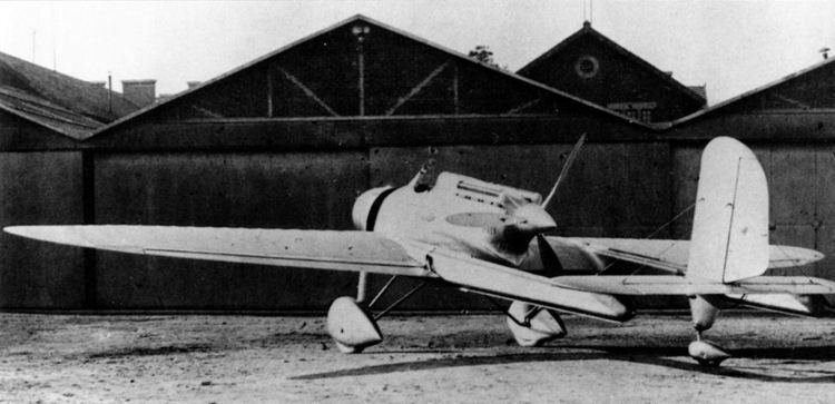
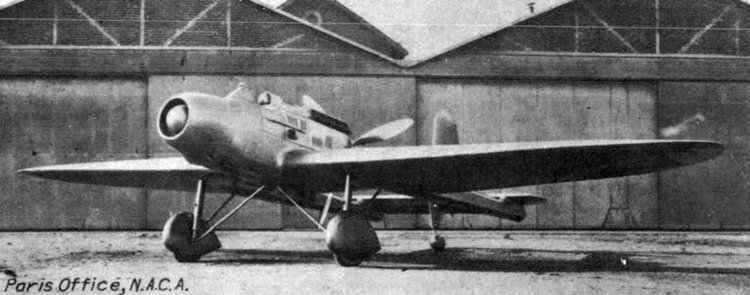
The Hanriot H.110 was an unusual pusher configuration, twin boom, single seat fighter aircraft built in France in the early 1930s. It proved to be slower and less manoeuvrable than its contemporaries and failed to reach production, even as the Hanriot H.115 after receiving a more powerful engine and cannon armament. From 1916 until 1933, the only Hanriot fighter aircraft had been tractor biplanes. The Hanriot H.110, a twin boom pusher cantilever monoplane was therefore a considerable departure from the past. It was designed to compete in the STAé (Service Technique de l'Aéronautique or Technical Section of Aeronautics) 1930/31 C1 (single seat Chasseur of fighter) programme. The all-metal H.110 had an open cockpit and engine in a short central nacelle. It was powered by a 485 kW (650 hp) Hispano-Suiza 12Xbrs supercharged upright water-cooled V-12 engine behind the pilot, driving a three-blade pusher propeller. The pilot's headrest was smoothly faired into the engine cowling. There was a circular Chausson radiator in the short nose ahead of the open cockpit, with a variable position central cone to control the airflow. The wings were built around two spars. The central 25% of their span, between the booms, had constant chord. Immediately outboard they had a wider chord and beyond were double straight tapered to rounded tips. They carried almost full-span, narrow-chord Frise ailerons. Forward, the slim, square section and untapered tail booms blended into the wings at about mid-chord, the aft ends carrying a constant-chord tailplane slightly above them. This had rounded tips and a central elevator with a trim tab. A central, single, tall, round-tipped, wire-braced vertical tail was mounted on in it. The H.110 had a fixed, split, conventional undercarriage with each spatted mainwheel on a faired, near vertical shock absorber and a rearward leaning strut together forming a V, laterally braced with an inverted V-strut attached near the under-fuselage centre line. There was a central tailwheel on a long leg under the fin. The H.110 began flight testing in April 1933. Tested against its smaller and lighter competitors, it proved slower and less manoeuvrable and was returned to Hanriot for modification. It flew in April 1934 as the H.115, with its HS 12Xbrs engine uprated to 515 kW (691 hp), a new four-blade propeller with variable-pitch and a revised nacelle, shortened forward of the cockpit by 360 mm (14.2 in). A 33 mm (1.30 in) APX cannon was now housed in a fairing below the nacelle as an alternative to the earlier pair of Chatellerault 7.5 mm (0.295 in) machine guns. With its new engine and propeller the H.115 was quicker than the earlier version, with a top speed of 390 km/h (242 mph). After more modifications over the winter of 1934-5 it returned to Villacoublay in June 1935 and was officially flight tested until mid August, but failed to attract a contract.
-
The Dyle et Bacalan DB-70 was a large three engine French airliner with a thick airfoil centre section which accommodated the passengers. Two fuselages, part of the centre section at the front but distinct further aft, carried the empennage. First flown in 1929, only one was built. In 1925 the large naval ship builders Société Anonyme de Travaux Dyle et Bacalan, established in 1879 and based in Bordeaux, developed an aircraft manufacturing interest. They built several all-metal prototypes incorporating very thick wings. The DB-70 was the largest of these and the last to carry the company name: Dyle et Bacalan ceased trading in July 1929, before the DB-70 had flown, though the company reformed as Société Aérienne Bordelaise (SAB) that same month. As a result, the aircraft is sometimes referred to as the SAB DB-70; the letter prefix DB was retained, though aircraft designed later by SAB used the AB- form . The DB-70 was a very large, all metal aircraft built, like all Dyle et Bacalan aircraft, largely of duralumin. As on the 1926 DB-10, the centre section of the wing of the DB-70 was extremely thick and twice the chord of the outer wings, with a chord/thickness ratio of about 25%. The layout of the two designs was different, though; the otherwise conventionally laid-out DB-10 had thick wings inboard of its two engines, whereas the DB-70 was built around its thick centre section with twin fuselages, developed from it rearwards, carrying the empennage. The centre section also mounted the three 450 kW (600 hp) Hispano-Suiza water-cooled inline engines and the pilots' cockpit and enclosed the passenger accommodation. The 9.25 m span wide (30 ft) centre section, the structural core of the DB-70, was based on four steel transverse spars, separated vertically by 2.30 m (7 ft 6 in), horizontally by 1.95 m (6 ft 5 in) and cross-braced into six frames, forming five transverse bays. The two pairs of outer frames defined the forward fuselages and the outer wings, engines and undercarriage legs were attached to the outermost frames. The centre engine was mounted on the central frame, positioned well forward of both the leading edge and of the planes of the two outer propellers. The whole structure was duralumin skinned to form an aerofoil section with a chord of about 10 m (33 ft), the lower surface continuing to form the undersides of the fuselages. The outer wings were mounted high on the fuselage sides, carried 3° of dihedral and were of parallel chord with rounded tips. Each was supported from below by a pair of struts mounted on the lower fuselage longeron. The fuselages were simple rectangular cross section structures, built around four longerons and tapering rearwards. They carried the horizontal tail surfaces, both between them and extending outwards. The angle of incidence of this 'fixed' tail could be adjusted in flight for trimming. It carried three linked and balanced elevators. Two rectangular fins carried balanced rudders. The DB-70 had a fixed conventional undercarriage with double mainwheels on V-shaped shock absorbing legs mounted on the lower longerons, with bracing struts to the centre of the centre section. This arrangement produced a wide undercarriage track of 6.65 m (21 ft 10 in). Sprung tailskids were placed the extreme ends of each fuselage. The passenger accommodation was a rectangular area within the deepest part of the centre section, 5.35 m (17 ft 6 in) long, about 9.5 m (30 ft) wide and 1.88 m (6 ft 2 in) high. The structural bays divided this space laterally into three: two outer, 10 seat cabins 1.80 m (6 ft) wide, each lit by 5 windows in the outer fuselage walls, and a central saloon with eight arm chairs grouped around two tables. For night flights, the seats in each of the cabins were replaced by 8 berths, reducing the overall accommodation to 24. Aft of this central area were toilets, a kitchen and baggage space plus corridor access to a floor trapdoor which was the principal passenger entryway. A 'promenade' ran the width of the centre section ahead of the seating areas, lit by glazed wing leading edges, with further passenger access doors at either end. Adjacent to it in the centre section leading edge was a corridor that allowed the third crew member, a mechanic, to enter the engine compartments for in-flight servicing. The two pilots sat in an open cockpit, fitted with dual controls, at the centre section leading edge. The first flight of the DB-70 was on 15 November 1929 from Merignac Aerodrome. Initial trial flights showed the aircraft could take off in about 120 m (400 ft) carrying a 5 tonne load. It flew around the airfield at Vincennes on both days of the National Aviation meeting held there in June 1930. Photographs show that modifications were made after the early flights, including the provision of external exhaust pipes and an increase in passenger window size, done by making the original oval windows into square ones. Only one DB-70 was built, though the military, four engine SAB AB-20 and SAB AB-21 used very similar airframes.
-
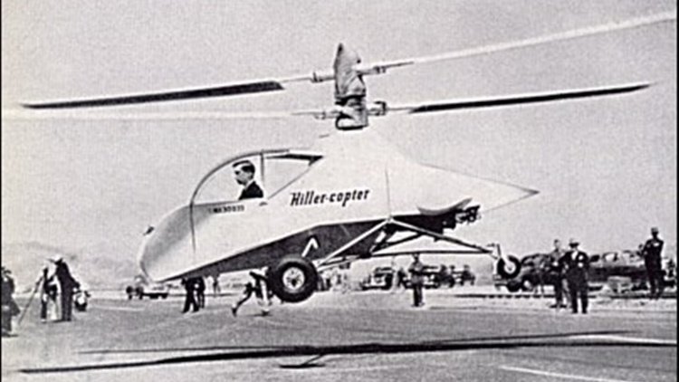
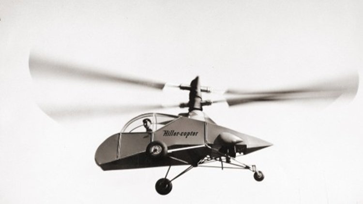
The Hiller XH-44 Hiller-Copter (Experimental Hiller, 1944) is an American experimental helicopter designed by Stanley Hiller. Stanley Hiller became interested in helicopters in the late 1930s, when he saw pictures of the Focke-Wulf Fw 61 and the Vought-Sikorsky VS-300. He bought every book on helicopter development that he could find, and in the early 1940s he began design work on the XH-44, at the age of 17. The XH-44 featured a pair of contra-rotating rotors which, in its original form, was powered by a 65 hp Franklin engine (de-rated from its original 90 hp). The engine was later swapped for a 125 hp Lycoming engine. It was the first successful coaxial rotor helicopter to be built in the United States, as well as the first helicopter to use all-metal rotor blades. The XH-44 tipped over on its first tethered test flight with Hiller at the controls, resulting in minor damage. On July 4, 1944, the XH-44 made its first untethered flight at the University of California's football stadium at Berkeley. The helicopter made an appearance during a public demonstration at San Francisco on August 30, 1944. The success of the XH-44 caught the attention of Henry J. Kaiser, who funded further development of Hiller's rotor system. Hiller donated the XH-44 to the Smithsonian National Air and Space Museum in 1953.[4] The helicopter was restored in 1974, and in 1997 it was lent back to Hiller and displayed at the Hiller Aviation Museum. The original XH-44 was later moved to the Steven F. Udvar-Hazy Center, with the Hiller Aviation Museum displaying a replica in its place. Number built 1
-
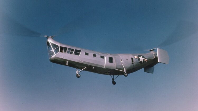 The Piasecki HRP Rescuer (also called Harp) is a United States tandem-rotor transport or rescue helicopter designed by Frank Piasecki and built by Piasecki Helicopter. The Piasecki PV-3 was adopted as the HRP-1 Rescuer by the United States Navy, United States Marine Corps, and United States Coast Guard. An improved PV-17 variant was later produced as the HRP-2. As one of the first transport helicopters in military service, the HRP-1 was capable of carrying two crewmen and 8–10 passengers or 2,000 lb. (907 kg) of cargo. It was first flown in early 1945, entered service in 1947. The prototype helicopter (designated PV-3 by Piasecki, though commonly known to test personnel as "The Dogship") first flew at Morton, Pennsylvania in 7 March 1945 following a development contract from the United States Navy in February 1944. The "Dogship" was a novel tandem-rotor helicopter with a fixed tricycle landing gear, powered by a 600 hp (447 kW) Pratt & Whitney R-1340-AN-1 engine. To ensure that the rotors did not hit each other, the rear end of the fuselage curved upwards so the rear rotor was higher than the forward rotor. The fuselage was constructed of ordinary mild steel tubing, filled out with wooden ribs, and covered with doped fabric. Following a series of mechanical incidents with the prototype, including stripped transmission gears, it was determined that use of common automotive parts in the helicopter transmission were inadequate to the severe loads imposed by flight; subsequent prototypes built after the war used stronger components. Two prototypes designated XHRP-1 were constructed; one was used as a static test aircraft and the other was used for development flying. The helicopter got the nicknames " Harp" and "flying banana", a name also carried on by its successor. Number built 28 Variants PV-3 Prototype tandem-rotor helicopter powered by a Wright R-975 piston engine, one built. XHRP-1 Military designation for two further PV-3s, one for static testing and one for flight trials. HRP-1 Production variant, 20 built including three HRP-1Gs. HRP-1G Three United States Navy HRP-1s for the United States Coast Guard. HRP-2 Metal skinned variant, five built.
 -
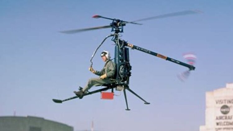 The Hiller ROE Rotorcycle is a single-seat ultralight helicopter designed in 1953 for a military requirement. A total of 12 were produced for the United States Marine Corps. And in 1954, the Hiller Helicopters was selected by the US Navy's Bureau of Aeronautics to build this design of a one-man, foldable, self-rescue and observation helicopter. It featured a two-blade rotor system. Its original empty weight was 290 lb (132 kg). The helicopter folded up and could be carried on a sled-like carrier by two people or could be air-dropped to pilots trapped behind enemy lines. The Marines did not accept the YROE due to its low performance, vulnerability to small-arms fire and the lack of visual references on the structure. This problem could cause the pilot to experience spatial disorientation at all but very low altitudes. The YROE or ROE never saw military service. In 1954, the United States Navy′s Bureau of Aeronautics selected Hiller to build its proposed design of a one-man helicopter. The XROE Rotocycle completed flight testing in mid-1957. It was demonstrated at the Pentagon in Arlington, Virginia, for military and other government officials in early April 1958. Production was by Saunders-Roe, which made five for the United States Marine Corps and five for Helicop-Air of Paris. A Porsche engine of 62 hp (46 kW) developed for the YROE completed trials by 1961. Number built 12 Variants XROE-1 2 prototypes built as Model 1033 at the Hiller Helicopter Plant in Palo Alto, California The first flight in November 1956 YROE-1 5 test versions built by British Saunders-Roe company One donated to the Smithsonian Institution after completion of its testing in 1961 ROE-1 5 production built by Saunders-Roe (built ten production models, including the five YROE-1s)
 -
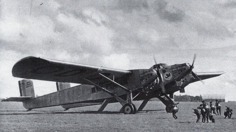
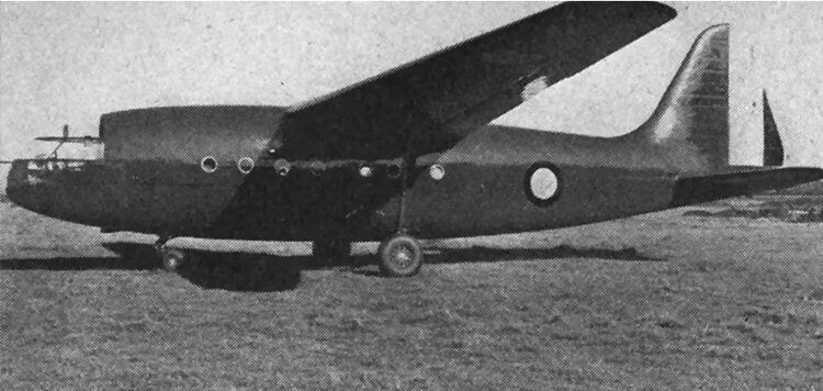 The Fouga CM.10 was an assault glider designed for the French Army shortly after World War II, capable of carrying 35 troops, later converted as a powered transport. The CM.10 was a high-wing cantilever monoplane of conventional configuration with fixed tricycle undercarriage. Flight trials with the glider prototypes were of mixed results with the first prototype crashing on 5 May 1948 whilst being flown by CEV Brétigny. A production order for 100 was placed with Fouga, but cancelled after only 5 gliders had been built. CM.100 (Specifications below) Undaunted, Fouga adapted the design as an airliner, adding two SNECMA 12S piston engines. Two of the production CM.10 gliders were converted to the powered version, CM.100-01, the first prototype (registration F-WFAV), was first flown on 19 January 1949, but no order resulted for this aircraft. It was later tested with Turbomeca Piméné turbojets mounted on the wingtips as the CM.101R-01. The second aircraft, which was converted as CM.101R-02, (registration F-WFAV), was first flown on 23 Aug 1951.
 -
An interesting article on the "Scariest aircraft of WWII". https://dailytopis.com/this-was-the-worlds-scariest-aircraft-during-ww2-2/
-
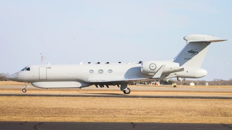
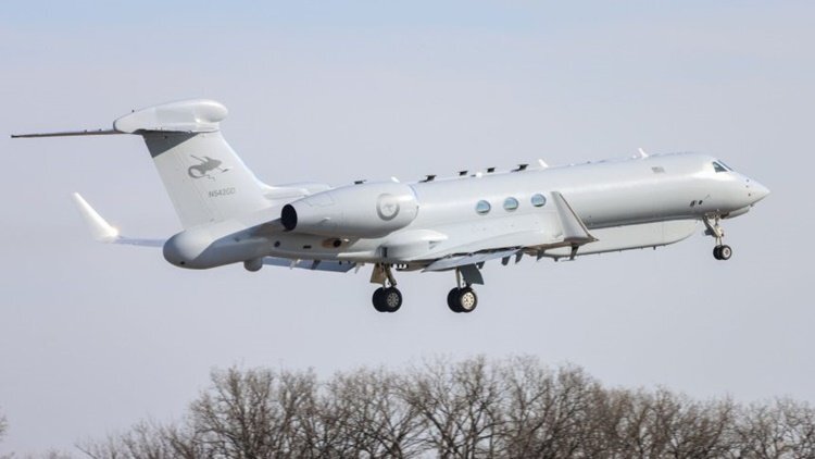
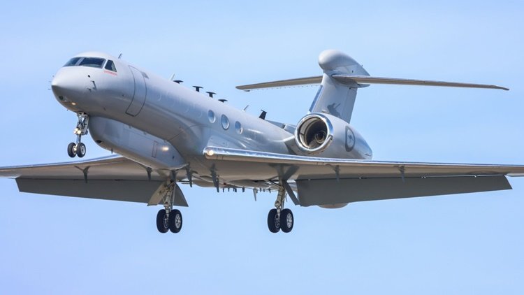
EDINBURGH SA: The first of the RAAF's new MC-55A Peregrine ISREW special electronic missions aircraft is inbound to Australia on its delivery flight. The aircraft, RAAF MC-55A Peregrine AU3 (US civil registration N584GA) departed Majors Airport in Greenville Texas where contractor L3Harris is located on Friday bound for Tucson Arizona before crossing the Pacific Ocean and landing at Joint Base Pearl Harbor Hickam at Honolulu in Hawaii on Saturday. The aircraft, flying under its US civilian registration number N584GA and callsign SAME55, is almost certainly inbound to its squadron home base at RAAF Base Edinburgh on Adelaide's outer fringe where its operator, the RAAF's Number 10 Squadron, has been based long term. While MC-55A AU3/N584GA is the first Peregrine airframe known to be actively under delivery to the RAAF in Australia, it was the third of four MC-55A Peregrines to be identified during the long and complicated systems design and development of the Australia-unique MC-55A Peregrine platform. The RAAF is acquiring four MC-55A Peregrine Special Electronic Missions Aircraft under the delayed $2.46 billion Project Air 555 (Intelligence Surveillance Reconnaissance Electronic Warfare (ISREW) Program, to equip the RAAF's No 10 Squadron which previously flew the small fleet of now retired AP-3C(EW) Orions, withdrawn from service in 2023.
-
I posted the Dreamlifter one in Silly Aviation Pictures on 29 Dec 25. I also pasted the vegan 747 a couple of years ago, but haven't gone back looking for it.