

old man emu
-
Posts
5,297 -
Joined
-
Last visited
-
Days Won
78
Content Type
Profiles
Forums
Gallery
Downloads
Blogs
Events
Store
Aircraft
Resources
Tutorials
Articles
Classifieds
Movies
Books
Community Map
Quizzes
Videos Directory
Posts posted by old man emu
-
-
5 hours ago, kgwilson said:
How can you calibrate something that is printed on the dial along with the numbers which are also immovable.
Probably a bad use of the word "calibrate". What I meant was that if you mark those "V" speeds on your altimeter, you calibrate it. You mark it so that you have boundaries that the indicator needle must be within, or not exceed depending on the required speed. What you are after is something that you can glance at and know without having to think that the needle is pointing where you want it.
When you start your engine, don't you quickly look at the dial to see that the needle is "In the Green", so you can carry on. It might only be during flight that you actually monitor the position of the needle to assure yourself that the oil pressure is not falling (leakage, or pump failure) or rising (blockage).
5 hours ago, aro said:The important V speeds Vs0, Vs1, VFE are IAS not TAS
ARO, I specifically wrote TAS because the Lift equation uses TAS, not IAS. Also I was referring to the illustrated ASI, which is probably more flash than the type you would use in an under 600 kg plane. It probably doesn't mean a hill of beans anyway, as very few pilots want to fly on the edge of the envelope. We all add a fudge factor.
-
Never try to remember something that you can look up in print. In this case the "in print" are those simple strips of tape.
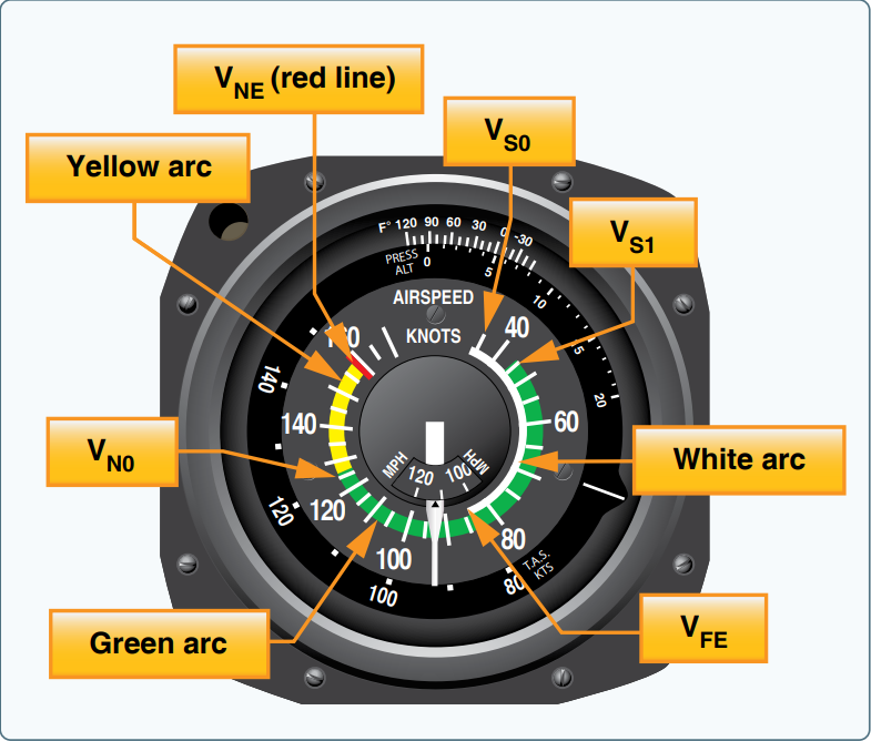
Isn't is amazing that airspeed indicators are marked with the white, green and yellow ranges out of the box, but no one ever says to "calibrate" them for your aircraft.

White Arc - Flap operating range
Green Arc - Normal operating speed in smooth and turbulent air
Yellow Arc - Operations in smooth are only.
Vso - Stall speed or minimum flight speed in landing configuration
Vs1 - Stall speed or minimum steady flight speed for which the aircraft is still controllable in a specific configuration
VRef - Landing reference speed or threshold crossing speed - The speed to be "over the numbers"
Vx - Speed that will allow for best angle of climb - Obstacle clearance speed
Vy - Speed that will allow for the best rate of climb
NOTE:
On the illustrated ASI, there is a moveable scale to allow for IAS to be converted to TAS. Remember that the Lift formula is expressed in terms of TAS, so if you have one of these ASIs that has a moveable scale, the markings for V speeds should be on that scale.
-
 1
1
-
-
I wonder how the landing fees at Bankstown and K-S in the 70s and 80s compare to what they might be today. hdus001 did not tell us how much the movement fees were for the whole trip.
-
While the hunt goes on for a barn find, those amongst us who enjoy making scale models of aircraft might like to tackle this
-
15 hours ago, facthunter said:
We used to get a heading off a turn from the runway alignment and intercept final at KS from it. on rwy 16
That was back in the Good Ol' Days when KS didn't have every daytime slot filled, and when you got back to Bankstown you ended up in the Royal Flying Club lounge for refreshments.
-
If I had USD15 I would buy the operator's manual. But let's wait until we can find one gathering dust in the back of an old hangar or shed.
-
2 hours ago, Yenn said:
Somehow birds do teach later generations how to avoid dangerous places.
I think all animals are able to pass on to their offspring a knowledge of the dangers of their environments. It is presumptuous of Man to think than no other animals can reason to some degree.
-
On 09/01/2021 at 12:08 PM, facthunter said:
How does a flock of birds or a school of fish know how to turn as if they are ONE entity
I did do some research later on and posted my results here
-
Yep. Mine was into Canberra during a flight from Mudgee via Parkes. I don't know why we didn't go up to Tamworth. My mate was chasing a bit of skirt from Tamworth and he often flew from Dubbo to Tamworth for meetings with her.
-
Apart from the electric motor which would drive the air pump, Link trainers don't have much in the way of "electronics". Movement was created through the operation of bellows. Since Link himself was a player piano technician, the design is an application of the operating mechanisms of a player piano. The material for restoring the bellows is quite readily available.
There are some valve electronics, but once you got hold of the manuals you could get some electronics genius, like Kyle, to recreate the old valve circuits with modern components. The parts manual is attached.
-
-
Prior to, and during WWII, the RAAF purchased 140 Link Trainers in order to speed the training of pilots in instrument flying. Under the type identification system, Link Trainers were given the designation A13, despite the traditional fear of the number thirteen. The logic seems to be that since these trainers would never leave the ground, there wasn't much fear of student pilots killing themselves in them. By giving the Link trainer a type number, time spent in simulated flight could be correctly logged as air experience. A list of the A13s can be found here. along with their histories http://www.adf-serials.com.au/2a13.htm
At the end of WWII the majority of the RAAF's Link trainers were either dismantled or sold off. A number were removed from RAAF active service, or handed over to Air Training Corps units and other aviation"cadet" type units. Lots of these Link trainers are on display in aviation museums around the country.
If we disregard all those in museums and cadet units, there are a lot of these Link trainers to be accounted for. A major purchaser was Kingsford-Smith Aviation around 1947. The unaccounted for trainers have to be somewhere. It would be great to get one and restore it. Maybe we could designate it A13-RecFlying.
Who is up to asking around to see if we can find a missing link?
-
1 hour ago, Jabiru7252 said:
It's all magic folks. Don't need to know this stuff to be a good pilot. Just the basics will do.
You are not wrong. It's just that this place is a good one to discuss the minutiae of aviation. Just as it's a good place to discuss famous or rare aircraft and all the other stuff we discuss. You learn stuff all the time. It maybe pushed to the back of your memory, but one day it will be needed to impress onlookers, or to destroy a Richard Cranium.
-
2
-
-
2 minutes ago, skippydiesel said:
am I close
One post too late. Missed by thaaat much!
-
 1
1
-
-
Laminar flow around golf ball. Either my eyes are better than yours, or my monitor is. I watched the video on full screen and I could in fact see a longer space behind the ball before the eddies appeared.
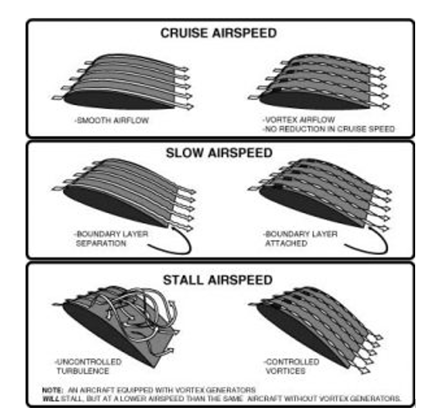
Vortex Generators. The impression I got from the images was that without VGs, at the stall, the airflow separated from the surface of the wing and never returns. With the VGs it still separates, but swirls back down to contact the wing closer to the trailing edge. That return to the surface must result in enough lift to reduce stall speed.
-
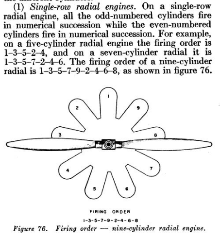
Odds or evens, the more cylinders the smoother the engine.
Think of it this way. If you are driving your car along a dirt road and hit a single pothole, you really feel it. But if you drive along a road with a corrugated surface, you can find a speed where the on and off again contact with the road surface appears smooth.
-
3 hours ago, Garfly said:
Warning: this content may only be comprehensible to OME and the other physicists among us
No formulas. No Algebra. No Calculus.
The video can be watched and understood by anyone with a grasp of conversational English. I think the hardest concept to understand was "laminar flow", but that was explained in simple terms near the beginning of the video.
What did I learn from it? I learned what a Reynold's number meant. I learned that a washed plane is a fast plane. It also reminded me that what a homebuilder does to create teh surface of wings will greatly affect aircraft response to airflow.
Included in the video is an explanation of how vortex generators work to improve performance and control authority at low airspeeds and high angles of attack. For more on that go to this site: https://microaero.com/
I also learned that if you want your balls to go further, keep them rough.
-
1
-
-
9 minutes ago, facthunter said:
You'd still have about the same imbalance which is what causes the problem. Nev
Can you please explain where the imbalance originates?
If a "normal" two-bladed propeller is balanced statically and dynamically, then one would think that the only source of vibration in an engine would be as a result of the intermittent application of force within the cylinders during the combustion sequence. That's why a six cylinder engine appears "smoother" than a four, and an eight smoother than a six.
I seemed to have forgotten to post Walter Everel's description of the principles of his propeller so here it is. The only thing that I would edit is his saying that "Aerodynamic thrust is balanced by the centrifugal force of the propeller". You know how I hate "centrifugal force". I'm pretty sure that the correct term is angular momentum of the propeller.
-
Don't forget that the Everel propeller was designed and made (by Sensenich) in the 1930s. You can see that the propeller was made from wood as was usual at the time. It would be quite simple to make the propeller from modern materials (carbon fibre) which would make it so much lighter.
Just look at the video of the single-blade props for the RC model. They are plastic. If not made from carbon fibre, the prop could be made from the same stuff as RC nylon props, which hold together at extremely high revolutions.
-
20 minutes ago, skippydiesel said:
In nature, where similar demands/objectives/environments are imposed, we see a tendency for animal shapes to "conform" ie be very similar.
Form follows function.
-
Actually, whether centrifugal force is a "real" force or an "apparent" force depends on your point of observation.
The difference between centripetal and centrifugal force has to do with different 'frames of reference,' that is, different viewpoints from which you measure something. Centripetal force and centrifugal force are really the exact same force, just in opposite directions because they're experienced from different frames of reference. Centrifugal force is an outward force apparent in a rotating reference frame. It does not exist when a system is described relative to an inertial frame of reference.
If you are observing a rotating system from the outside you are observing from an inertial frame of reference. Standing watching a kid swing a ball around his head on a string, you see an inward centripetal force acting to constrain the ball to a circular path. The ball is kept in its circular path by the centripetal force exerted along the string to the kid which is preventing the ball from going away from the kid. There is no source of a force to resist the pull towards the kid, except the inertia of the ball due to its velocity.
Ball in circular motion – rope provides centripetal force to keep ball in circle. If the rope breaks the ball continues in straight line with velocity at the time of cutting the rope, in accord with Newton's law of inertia, because centripetal force is no longer there.
However, if you are part of the rotating system, such as if you are in an aircraft doing aerobatics, you experience an apparent centrifugal force pushing you away from the center of the circle, even though what you are actually feeling is the inward centripetal force that is keeping you from literally going off on a tangent.
The whole misconception that centrifugal force exists is because people do not specify the frame of reference from which the observations are being made.
-
10 minutes ago, IBob said:
forward thrust generated by the blade would tend to tilt the blade forward on the hub.
I don't know the answer to that.
As for the counterweight, I believe that is simply there to provide a balancing force for the single blade. Just like you put a multi-bladed prop on a balancer to make sure that it doesn't vibrate.
-
32 minutes ago, skippydiesel said:
your disturbed/undisturbed air observation, would likely be true at course pitch & relatively high forward speed but what happens at fine pitch on TO role & climb ?
You have to consider the path of the blade. If you agree that in simple terms the path of the blade when the aircraft is moving forward describes a helix, Geometrically, a screw can be viewed as a narrow inclined plane wrapped around a cylinder. We can compare the interaction of the blades with those of the threads of a screw.
The blade of a propeller can be likened to the flank of a screw thread.
The flank of one thread does not pass collide with the flank of the following thread. Thus the the "following" blade of the prop does not pass through the disturbed air of the "leading" blade.
-
22 minutes ago, IBob said:
Would not the rotating centre of thrust impart a corkscrew motion to the nose of the engine/aircraft (requiring reinforcement of bearings and mounts)?
In the AOPA video at time 2:18 you see that the prop seems to be attached to some form of universal joint so that it can move. I would think that the universal joint would allow the blade to come to an equilibrium position. Vibration is a result of a rotating object being out of equilibrium. Once that equilibrium was established, I would expect that the forces on the crankshaft of the engine would be of the same order as those caused by a regular multi-bladed prop.
Apparently the universal joint allowed the pitch of the prop to alter with the power output of the system, so that the blade would go to a finer pitch at high revs, then coarsen off as revs decreased. I think that is what the 1930s video is trying to show - the plane with the finer pitch accelerates faster and climbs quicker.


Question
in Instruments, Radios and Electronics
Posted
More than half the electrical problems with any vehicle are caused by poor ground return wiring. As Danny says, if you use one wire going back to the ground block from many individual points, use a lot thicker wire. Don't scrimp on the thickness of earth wires.