IBob
-
Posts
3,148 -
Joined
-
Last visited
-
Days Won
27
Content Type
Profiles
Forums
Gallery
Downloads
Blogs
Events
Store
Aircraft
Resources
Tutorials
Articles
Classifieds
Movies
Books
Community Map
Quizzes
Videos Directory
Everything posted by IBob
-
Thanks Skippy. Yep, I was being a bit lazy..........but am also finding only a small subset of Gates products routinely stocked in NZ. For instance, Repco here have never heard of 8GTH, I have emailed Gates asking where I may get it.
-
Rubber replacement here. I have the ICP SS oil and coolant lines, which require short hose terminations. Am currently trying to source Gates 8GTH here in NZ, it looks like a good fit for the oil. As suggested at the start of this thread, so thanks for that. Does anyone have a recommendation for the coolant, which requires similar short straight bits of 25mm hose?
-
Yes....but do we get to shout at each other???........................😬
-
Kavlico, Fuel Pressure Sensor, PN 103755-000
IBob replied to skippydiesel's topic in Instruments, Radios and Electronics
Skippy, so after it began to play up, you flew level again at normal power, and it still played up? I ask because on my aircraft, the airflow around the cowl changes (as you would expect) with different aircraft attitudes. The result in my cases is that in a hard climb the naca scoop on the top no longer scoops. A long shot, I know, but I thought I would tip it into the mix.... -
Okay, just saw your above post, Dermot. Are they now using 577 all round?
-
Unless Rotax have changed it, the elbows into the water pump take Loctite 243, while the elbows into the heads take Loctite 480. I repositioned the elbows into the water pump using a dowel and a propane torch, as you describe. But I did it with that part of the water pump off the engine and held lightly in the soft jaws of the vice. It felt a bit amateurish, but it worked. Due to an error not of my making, I ended up having to replace one of the elbows on the underside of the heads......and that wasn't easy. As I recall, I ended up using acetone and one of those gun cleaning brushes to clean out the threads in the head. As noted, those elbow threads are very fine......and they are also 'soft as butter'.
-
bobcharl I posted more pics before this last post.
-
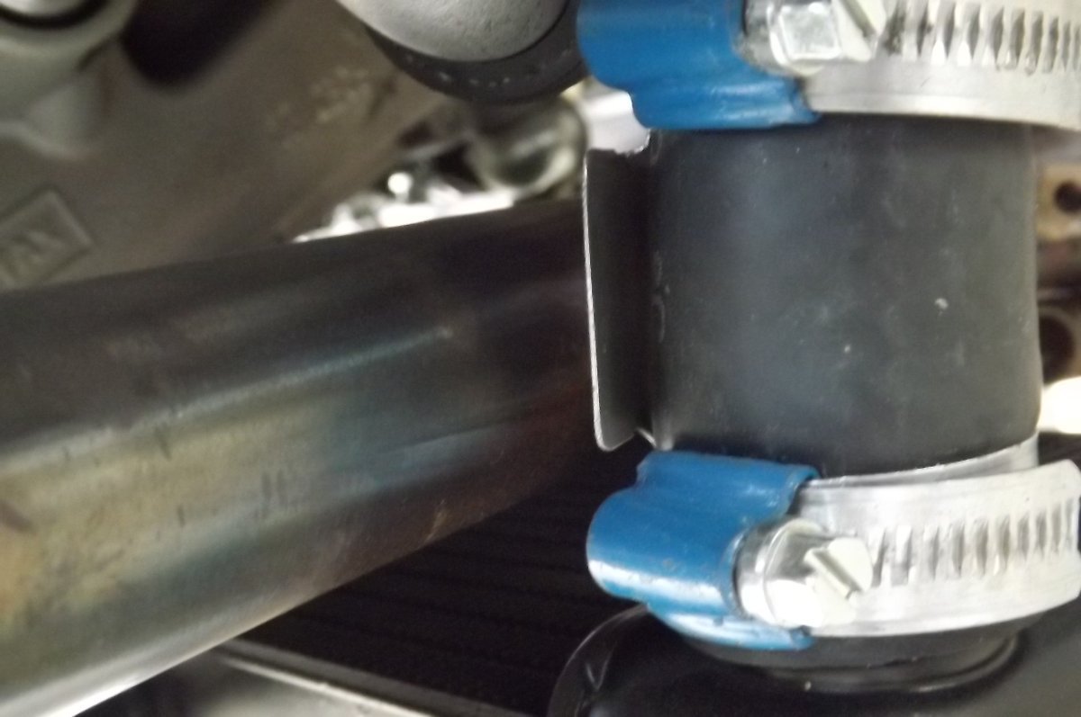
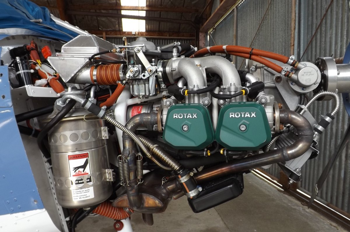
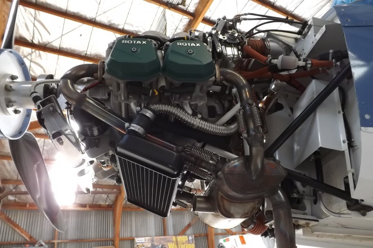
BTW, the hoses at the radiator ran quite close to my front exhaust pipes, so I inserted little aluminium shields. You can't see clearly here, but they are stepped out so that the shield stands away from the hose, with air passing both sides of the shield. My thought was to protect the hose from the radiated heat of the pipe. I did that on both sides:

-
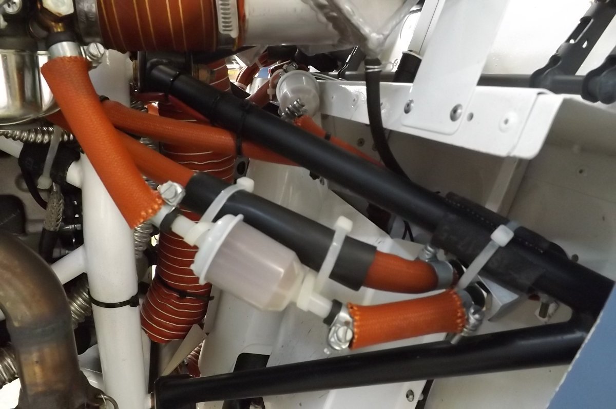
Ah, okay. here you can just see it making it's way through the engine mount and up just to the rear of the engine mount (ignore the thinner corrugated pipe at top LH, that is oil). It then bends forward just under the top tube of the engine mount, where the 'rubber' connector hose is clamped on, then to the coolant reservoir.
-
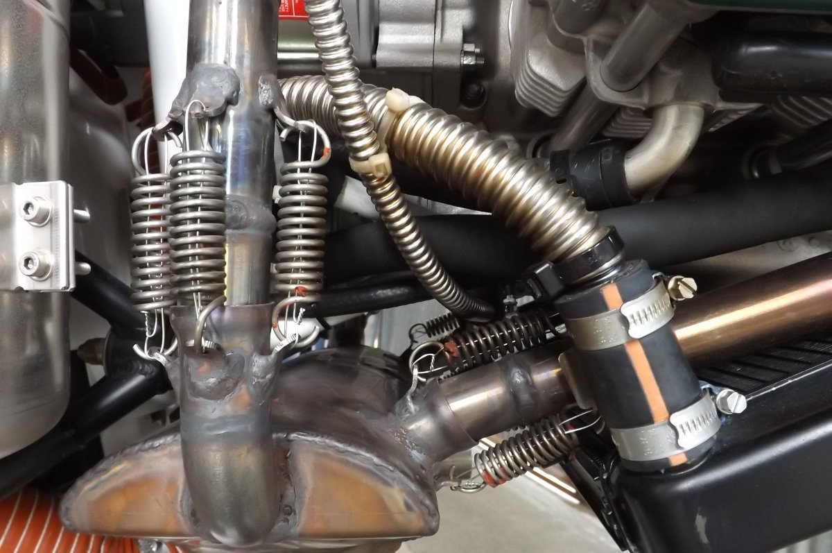
Hi bobcharl, I don't recall the RH tube being difficult, but it's been 5 years since installation. Unfortunately I can't show you the rear of the motor, it's hidden by the airbox and associated scat tubes etc. Assuming you are referring to the big pipe from radiator to pump, the spigot/junction at the pump can be bolted on in various positions, I may have turned mine to better accept the pipe. This is the best pic I have from the RH side, but I don't think it offers any more info than the previous pics:
-
Kavlico, Fuel Pressure Sensor, PN 103755-000
IBob replied to skippydiesel's topic in Instruments, Radios and Electronics
Well, Skippy, you're not short of advice and suggestions. Time now to actually troubleshoot the problem? -
Kavlico, Fuel Pressure Sensor, PN 103755-000
IBob replied to skippydiesel's topic in Instruments, Radios and Electronics
Thruster, I take your point, but I don't think it's that clear cut: what Skippy is reporting is intermittent apparent pressure drops. It seems to me that could be either pump or pressure sensing: if the sender is failing, it is possible that it does not respond reliably to the (lower) pressure of the mechanical pump, but does respond to the (higher) pressure of the booster. That's why I think it would help, if possible, to determine whether it is pump or sender/circuitry before shopping for a replacement. -
Kavlico, Fuel Pressure Sensor, PN 103755-000
IBob replied to skippydiesel's topic in Instruments, Radios and Electronics
Yes, that occurred to me too, Skippy. That's why I suggested borrowing a steam gauge if you can: identifies whether the problem is the fuel pressure or the sensing. And if it's any consolation regarding location, I see the Kavlico unit boasts 'Outstanding Shock & Vibration Performance' and an operating temperature range from -40 to 125'C (depending on seal material). -
Kavlico, Fuel Pressure Sensor, PN 103755-000
IBob replied to skippydiesel's topic in Instruments, Radios and Electronics
These are certainly considerations, Nev, but I don't entirely agree: our refrigeration ones were mounted into pipework on very big ammonia compressors, most of which run 24/7 until overhaul. Having said that, the 0 to 15PSI sender for the fuel is far more delicate than the oil pressure sender, by a factor of about 10. Personally, I would not be mounting it in the engine bay, for reasons not only of heat and vibration, but also because these are gauge pressure units that rely on also sensing a steady and accurate ambient pressure. -
Kavlico, Fuel Pressure Sensor, PN 103755-000
IBob replied to skippydiesel's topic in Instruments, Radios and Electronics
FWIW, I would say $300 is about the going rate for an economically priced transducer (sender). They come in: 2-wire, (loop powered), 3-wire, as this one is, 5v/0v/signal (output) 4 wire, power/0v power/Signal+/signal- (less used nowadays) This one has a 5V power in, and gives an output signal of 0.5v to 4.5V which is presumably 0 to 15PSI (though I note elsewhere that Dynon say you won't see anything below 0.5PSI.) So any sensor, suitable for use with petrol, with those operating parameters should be a direct swap-in. Depending on how far you want to dig, and on what adjustable parameters your Dynon offers, you could also swap in something with different parameters. For instance, the oil pressure transducer on the Rotax has an output signal of 4 to 20mA, (which is an industry standard) and it's quite possible the Dynon can be configured to accept that. All depends what Dynon setup you have. 0 to 15PSI is a good range for 912 fuel pressure unit. These senders are inclined to fail if the pressure exceeds their max rating. Typically we used to specify them as max pressure x 2, so for instance in a refrig setup where we might see 12 or 13 bar, we would fit 25bar transducers: that gave as a good degree of accuracy, with plenty of pressure safety margin and excellent reliability. One other note: some refrig enginerooms might have 20 to 30 pressure transducers over multiple compressors and the various vessels. Things may have improved now, but a few years back, of those 20 to 30 we would often get 1 or 2 that failed almost immediately. Of the rest, if they lasted a week, they gave no trouble after that. -
Kavlico, Fuel Pressure Sensor, PN 103755-000
IBob replied to skippydiesel's topic in Instruments, Radios and Electronics
I had a lot to do with pressure transducers over the years.....in industrial refrigeration and hot water systems, also in hydraulics etc. I note from the P255 data sheet: https://www.mouser.com/datasheet/2/657/sensata_p255_stainless_steel_pressure_transducer_d-1769810.pdf that it's principally for dry media, with Note 1 saying "For wet conductive media please contact us." It also notes that the internal seal needs to be compatible with the media. In short, I would be checking with the manufacturer that what you are looking at is compatible with petrol. -
Kavlico, Fuel Pressure Sensor, PN 103755-000
IBob replied to skippydiesel's topic in Instruments, Radios and Electronics
Skippy, any chance of getting your hands (temporarily) on a steam gauge? You could then identify whether you have a fuel pressure problem or a fuel pressure sensing problem. -
Skippy, two bathroom extractors moved the right amount of air. They were 6", not the little 4" jobs. I think because they vented directly out through the (wooden) wall of my workshop. The owner who very kindly lent them had less luck, probably because he had them running out of his hangar through long spiral wound ducts. And as noted, I turned off the heater before loading the gun. It sounds like you built the Rolls Royce. My setup was a lot less sophisticated......but (more by luck than good judgement) it did work well here at the time.
-
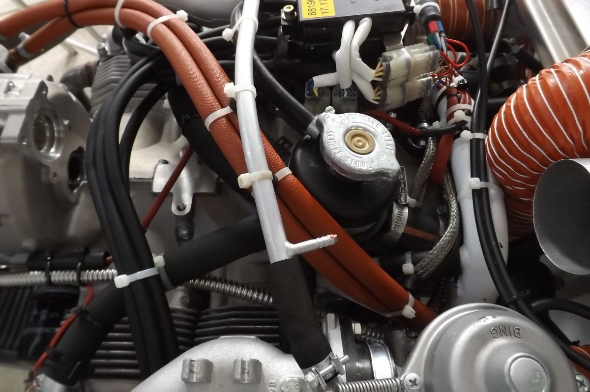
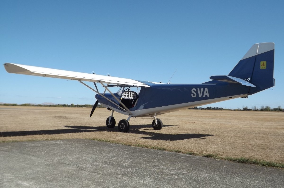
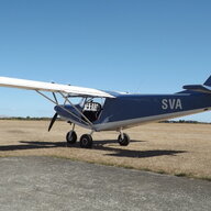
In my opinion, some kit builds are badly let down by poor choice of colour and layout. Which is kinda sad, given the care and the hours that go into a build. It took me a long time to settle on what I wanted, and I spent hours over the final months looking at online pics of this aircraft before deciding on the layout. The online stuff is gold when it comes to seeing how a layout actually looks from different angles. Then I had trouble finding the colour: I knew I wanted blue, in the end I got a friend to help go through the housepaint colour cards at the hardware store, then I got the colour mixed. The layout is very traditional Savannah. I stuck with that as I think the white underside makes the aircraft look less heavy in the belly. And it's simple as it just follows the overlap in the skins. For the white tip of the vertical stabiliser, that looks right if it matches the angle of the forward strake. And another builder suggested that the registration looks best if applied fairly far back.......so I did that. Also it's on straight (and surprising how many aren't). What I didn't do was fiddle with colours and layouts on paper. First, you never actually see the aircraft in the side elevation often used for that. And second what may look good on paper can't be relied on to look good in real life.
-
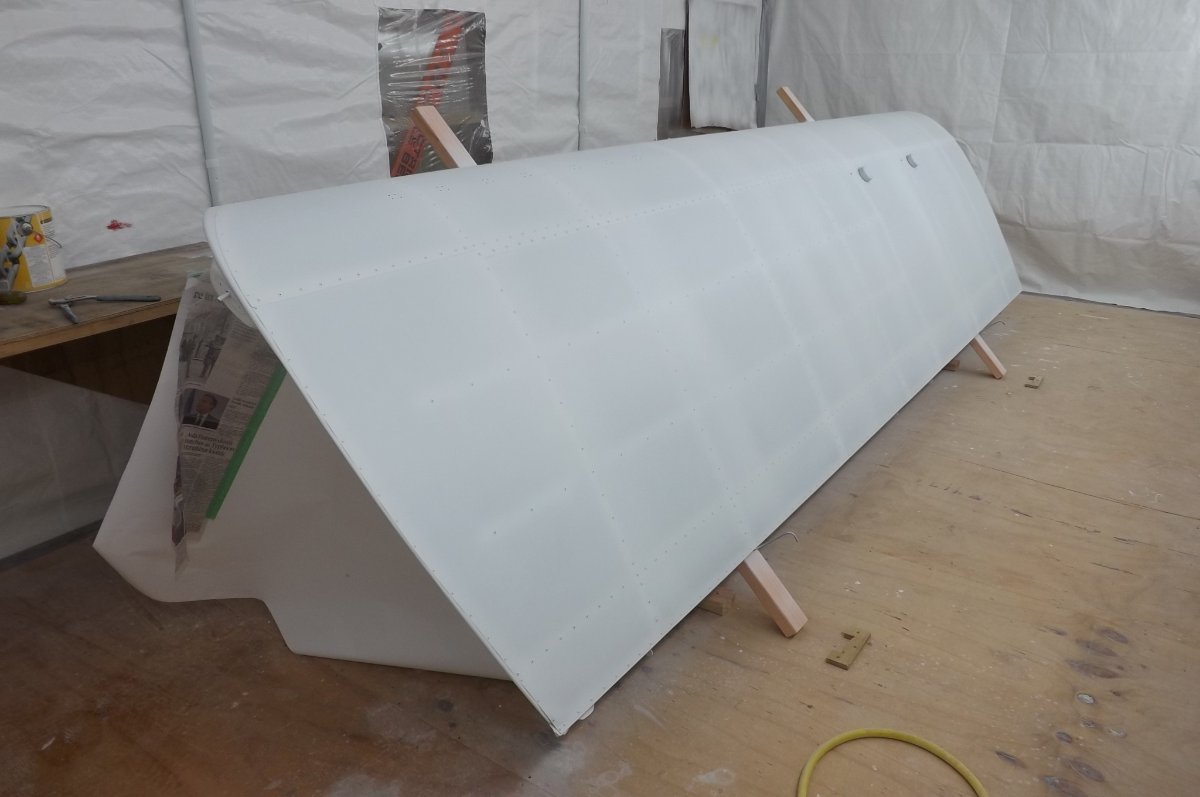
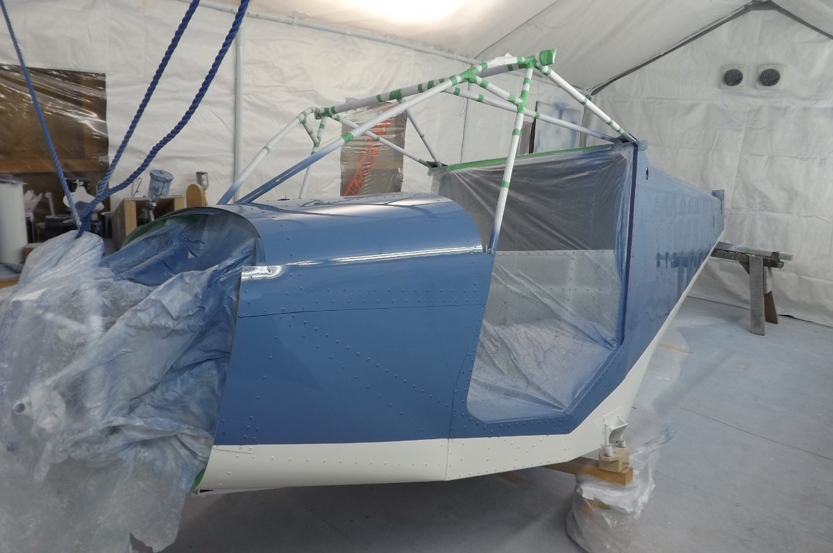
I bought a car parking tent and erected it in the workshop. It was early spring, so heating was required. At one end of the tent I had two bathroom extractors venting to the outside. At the other end I cut a hole to take a 2.3Kw electric radiator...one of those cheap ones on little wheels. So with the fans on, air was drawn into the tent via the radiator fins. This gave steady gentle air movement that didn't kick up the dust. In the 'booth' I had a cheap wall thermometer. With aircraft part/s in place, I would switch on radiator and fans, then wait until the temperature stabilised at an appropriate level: as I recall, I would suit up and start mixing once I had about 23'C. The painting itself is pretty quick, I think I turned off the radiator before picking up the gun, as there would be plenty of residual heat in the radiator. This worked well for me. As mentioned by others, you need lots of light. This may not be essential for skilled painters, but I found the only way I could see what actual finish I was getting was to move my head so as to get direct lighting reflections off the surface. With just a few points of light you can't do this. I had lighting all down one side of the tent, that worked okay if I ran round the other side of the job. In a perfect world I would have had lighting down both sides. And if you look at professional high quality spray booths, the walls and ceiling are solid banks of lighting. (As an aside to that, if you get a 'dry' spot or area (too much air or gun held too far away) you can sometimes remedy it by loading up quickly with thinners and applying a light overspray of that. But you do have to be quick to spot it, before the paint hardens.......which requires that good lighting.) So, yes, lighting: you can't have too much. As a complete amateur (I once applied a coat of paint in an orange-peel finish to a Fiat Bambina, 40years ago, and that was it) I figured I would need all the help I could get. So I spent some time making supports to hold the wings tilted up towards me, as that was the easiest angle to be working the gun. And I rotisseried the fuselage with a suspension rope round the engine mount, which allowed me to paint it in four stages. Initially I had too much air at the gun, and had to clean back one complete wing underside and start again. I bought an air gauge to go on the gun, as the gun pressure is not the same as the compressor when you are spraying. Once I got that sorted out, and with careful focus on gun distance and speed, it went quite well. I did the colour last, and found it much easier to see how that was going on than with the white.
-
There are flow rate calculators for both types on line. I haven't run the exercise, but the corrugated pipe supplied with the Savannah is presumably sized correctly, as it has no problem providing adequate flows and cooling. I believe corrugated pipe does have a sharper 'cutoff' once laminar flow is lost due to liquid velocity. Which would make sense. Bobcharl, as I recall, with the pipe that goes up to the coolant reservoir, I had to complete the shaping of it in place, as when I preshaped it I then couldn't thread it into position.
-
Skippy 1. Unnecessary potential failure points. I agree that at first sight 'rubber' termination of metal hoses could seem, in principal, messy and over-complicated. I guess that should be weighed against the benefits in practise.....and whether these additional points do actually fail. In practise I feel the metal pipe does a good job of making the required shapes in the Savannah engine bay. And I'm comfortable with those terminations. 2 & 3. Spot on. As noted above, another member here just pointed out that those filters are no longer acceptable. I have thanked him.......and now you......and will sort that out.
-
Moneybox, I have just been advised that the filters you see there are no longer to be used. So, I'll be getting onto that. The hose is the correct size, as I recall, for the splitter and the carb spigots. I can't tell you offhand what size it is. I can tell you that I did the original flow testing via them, and it was very much more than adequate.
-
bobcharl, the flexible SS radiator 'hoses' work fine. My kit was despatched Dec 2014 with them ,and so far as I know they are still supplying them: if there was a problem I'm pretty sure we would have heard by now. To avoid chafing, it's not difficult to secure them with cable ties, threaded through a short 'bead of regular hose to space them from the securing point. And they have the advantage that you can work quite a tight bend into them without flattening or collapse, as regular hose does when bent tightly. So makes for a very neat compact installation. You still need regular hose and hoseclips to make the junction at the ends.