pylon500
-
Posts
1,423 -
Joined
-
Last visited
-
Days Won
9
Content Type
Profiles
Forums
Gallery
Downloads
Blogs
Events
Store
Aircraft
Resources
Tutorials
Articles
Classifieds
Movies
Books
Community Map
Quizzes
Videos Directory
Everything posted by pylon500
-
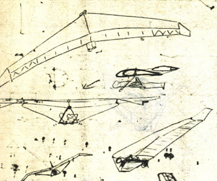
I think I can picture what you're going to do, I was going to go a different way back in my hang gliding days, with a high aspect rigid I wanted to build. I think some one else may have tried it already somewhere, where ailerons (only, as pitch is ok via weight) were connected to a floating lift cable system, that was then linked to the aileron belcranks. This meant that it still had the A frame 'wiggle' modern kites have, but the wiggle drove the ailerons instead of the crossbar. I later realised that this could run away with itself, so the ailerons needed to be mass balanced, and maybe even have anti-servo tabs.

-
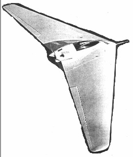
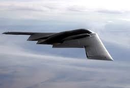
Actually, the B2 bomber is probably a bit of a red herring, as it most likely flies tail heavy with a negative pitching (normal) section, and relies on computer stability in pitch to make it flyable. It also uses drag rudders, as do most of the other 'finless' flying wings, so really they defeat their own purpose. Might as well just put a long skinny fuse out the back, and stick a tail and fin on it... But as for passive (no rudder) winglets, not a hell of a lot of effect.
-
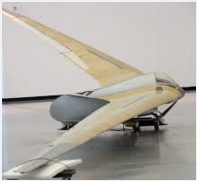
Directional stability, and the need for vertical devices for said stability is dependant on wing sweep. The more rearward sweep, the less need for vertical surfaces. Swept forward to straight flying wings need vertical surfaces, by the time you get to around 30º sweep back, no vertical surfaces are really needed, especially if there is any dihedral still present. Winglets on a swept flying wing would actually be counter-productive, unless they actually turned down. All these variations do and have existed, as well as those that technically didn't need tip fins (or winglets). And an example of a swept flying wing that probably didn't need tip fins, But as some here would say, it looked cool....
-
Pretty much. I think we all discussed this back in another thread after I found some debatable comments on a NASA youtube. http://www.recreationalflying.com/threads/new-theory-on-how-planes-fly.143310/page-3
-
Actually, when you look at his diagrams, what he's really come up with by trimming the lower wing surface up to join the upper surface, is an elliptical wing tip as per spitfire. Oh, hang on, the Spitfire came out before Hoerner.... In fact, the DeHavilland Rapide, Comet, Albatross even beat the spitfire. But as for winglets, I believe they can be useful, even on slower aircraft (gliders come to mind), but it is a close run thing between blending out the tip vortex via a washed out tip vs a correctly designed winglet, where you have to balance the wetted area drag used to gain the the tip vortex drag reduction...
-

DooMaw - building a STOL
pylon500 replied to Head in the clouds's topic in Aircraft Building and Design Discussion
Guess we could call it the Atlas? -
DooMaw - building a STOL
pylon500 replied to Head in the clouds's topic in Aircraft Building and Design Discussion
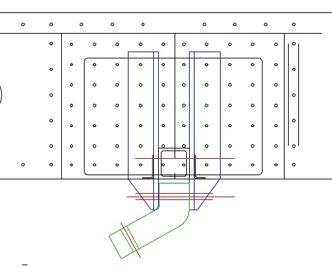
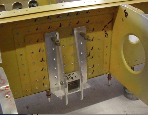
So that being the case, what are your plans for the wing end of the strut? I am planning on what I'm calling a 'double articulated' wing fold (folded back and swung down, as on yours and M61A1's machine) on Planet47's machine. To that end I was looking at the system used on an Italian machine called the 'Groppo Trail' (similar in appearance to my Stollite) until I saw the actual aeroplane at Oshkosh in 2013, and was not totally impressed.. Things that had me concerned; All flight loads taken by the threads of wing attach bolt, Wing fittings taking flight loads through a 'diaphragm' style structure, not in shear, Bolt cannot be 'tight' or clamped to allow wing to fold. (Sorry if photo's are a bit confusing, 1st photo is LEFT wing folded, 2nd photo is RIGHT wing rigged.) On the whole I was a bit disappointed in the Groppo Trail, being a little more agricultural than first thought. Having said that, the attach system I've come up with for the 'Planet Pusher' is probably overkill... Discuss?
-
DooMaw - building a STOL
pylon500 replied to Head in the clouds's topic in Aircraft Building and Design Discussion
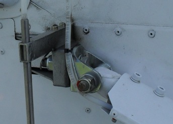
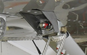
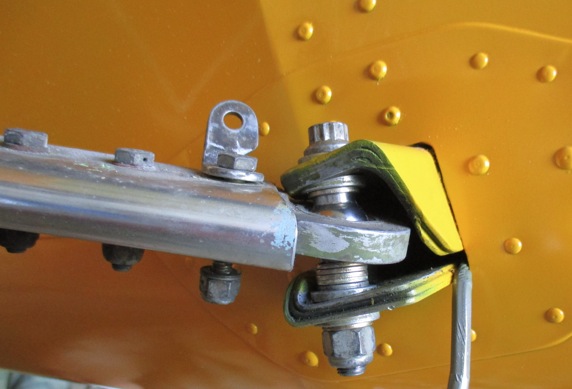
I hope this doesn't cause a huge problem, but if you have the strut fitting pivot bolt angled to be square with the strut, what are you doing to align the bolt, when the wings are folded back? The Kitfox (and it's clones) keep the bolt vertical, in the axis of the wing fold, and have the strut attach fitting angled on the strut. Because the strut to spar angle on my Stollite was angled, I opted to use a ball joint style fitting to make up for the misalignment. Wing is folded in this view.
-
If anyone hears of the funeral arrangements, could they post here (and/or if it is going to be held private) please? I'm sure that many people will want to go..
-
Or carbi ice?
-
This is a bit of a worrying development. Performance is nice, but looking good is more important?
-
If Taree council is anything to go on, I wouldn't be holding my breath.... There is land around Taree airport that could be developed, Like my site, but the owners of the various lands have not had much luck in trying to rezone or modify usage, so nothing has happened there. On top of that, the council then decided to develop more hangar space on the airport, and fix various problems with drainage and levels. I hear the works cost somewhere around the $2.5m, has around 10 sites available but all are priced as mentioned above, as commercial sites, even though many locals have determined that the sites are not really big enough to be effectively commercial; http://www.aircraftkits.com.au/documents/Taree%20Report%20May2015.pdf Add to that the fact that the earthworks did little to help the drainage problems, and you begin to wonder if councils have any form of competence...?
-
Unfortunately, I doubt that the winglets fitted to the jabiru's do anything useful at all... They are too thick, have the wrong section, and have been fitted to a wingtip that is already using a totally different aerodynamic technology, ie; turned down Hoerner style tip.
-
It just gives you that numb feeling all over, like, how much of this can we take?
-
Live prop nearly kills a pilot
pylon500 replied to rick morawski's topic in AUS/NZ General Discussion
Welcome to impulse magneto's... -
And being a control zone, all us ultralight people will have to drive in....
-
Plane spotting on steroids
pylon500 replied to rankamateur's topic in Aircraft Incidents and Accidents
I can just imagine CASA granting someone an AOC to fly into here....... NOT! -
Yes, often an 'inflow' straightener is used to sort out any turbulence generated from the intake to the fan, to give the fan 'clean' air to run in. This is often a problem with pushers, the aeroplane flies in clean air, but the prop gets dirty air, which is noticed as 'noise' from pushers.
-
All power to the students, and the state, which no doubt put up the cash for materials. But, and there's always a but, two things I noticed; Looking at the way it's flying in the video, and as has been said above, I think it's using all the power it's got, and it's not really zooming around the sky? (This from an aeromodellers perspective) Not sure if it would get off the ground with two people in it...? The other thing I noticed, which may go some way to curing the first observation, is that they are using a multi-blade fan, as you do, but don't appear to have a flow straightener after the fan? A propellor relies on having as much diameter as possible, thereby becoming a wing travelling through the air generating forward lift (or deflecting thrust backward for the non Brunellians') but only creating a minor amount of swirl around the fuselage. A smaller, faster turning fan needs more blades to absorb the power, but in so doing induces a fair amount of swirl down the tail pipe, losing direct velocity and making the tail pipe appear longer. A flow straightener will redirect the flow directly aft, adding to thrust.
-
DooMaw - building a STOL
pylon500 replied to Head in the clouds's topic in Aircraft Building and Design Discussion
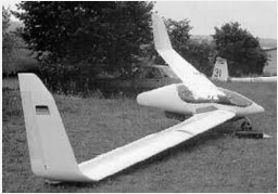
Yes, very fiddly little build.. Had a similar problem on my Stollite, having the rudder on top of the fuselage and tailwheel below. Solved mine by splicing the cable, but then running all four cables over four pulleys to maintain tensions, yes, springs at the tailwheel attach; Not really as easy as it looks because of the cables following the taper of the fuse requiring the pulleys to be at slight angles. (Thought I had a photo inside the fuse?)
-
You remember that one? That followed on from an earlier concept; Even started some drawings for it; Only got a few bits made..... Too many projects....
-
As you say, from a technical standpoint, 400 odd horse power to do around 150 knots, yeah, not efficient. But as someone else pointed out, we're only flying ultralights for fun, just imagine the looks when you roll up in something like this !!! And for my next project;
-
DooMaw - building a STOL
pylon500 replied to Head in the clouds's topic in Aircraft Building and Design Discussion
G'Day HITC, Don't panic, but I have the following for you to consider; Just looking at your elevator linkages and realised you've had to go the 'lessor' way of having a 'push for up' tube, instead of the preferred 'PULL for up' system. I know various others have gone this way as well, Lightwing and Foxbat to name a couple, but they have made up for it in different ways... Lightwing uses a fairly large diameter tube with the thinnest wall they could get, while Foxbat use two shorter tubes via an idler. The problem stems from the possibility of flex in the push tube that could induce further travel under G load, or in an extreme case, failure of the tube in bending while under the compression load of movement when subject to G load induced by said movement. While this may seem a bit of a stretch as a failure mode, consider; A STOL approach with full flap, stick already half way back to compensate pitching moment of flaps (ie compression load on tube), an unexpected downdraft requiring a sudden application of full elevator, elevator hits it's movement stops, further application at the stick adds higher compression load to tube, a moderate to heavy touchdown (momentary 5~8G impact not impossible), elevator tube now 5~8 times heavier causing it to flex out of alignment, added to the existing compression load already applied, the tube buckles to the bottom of the fuselage thus changing it's original length. This all took half a second. Now the aircraft rebounds into the air, the flaps start a pitch-over movement, added to a quick fore/aft movement of the stick to try and correct the bounce but because the elevator tube is now a little shorter, the pitch-over is exaggerated, another more violent and stronger back stick is applied, but instead of getting up elevator, the tube fails and the aircraft is nose down, low and with no pitch control !! It could be said that a similar problem could stem from having a 'pull-up' tube when G load is applied, where flex would shorten the tube thereby inducing more pull and hence higher G! Granted, but the tube will not flex as much when under a tensile load as opposed to a compressive load. Still, all you need to do to protect from the above is support the tube so that it can't flex out of alignment, either with a swinging cable, or as it looks with an 'under' pivot point at the stick end , and an 'over' pivot at the elevator end, there should be a neutral point somewhere along the tube where there is no vertical movement, and you could fit a roller or some sort of guide to maintain alignment. I remember the Pilatus B4 used felt guides for the elevator push tubes where it passed through the various bulkheads. Did tend to squeak when they got dry.... Sorry if I haven't made these comments earlier. -
There is another one out there, that has also flown, here's one of the test flights; And if you browser can translate Russian, here's some of the build forum (Russian EAA); http://www.reaa.ru/cgi-bin/yabb/YaBB.pl?num=1287751367/0 Corvette V8 driving two fans..... not quite RAAus
-
I think you can class a ducted fan as a propellor....? Hope so, cause I've got a few ideas... "Wing area; 8.5m² (23.6 sq ft)" ?, more like 91.4 sq ft I tend to agree, probably more like 20 Lph. With a 1000cc bike engine, it's probably only just putting enough thrust to get airborne with two people in it, but if you've got the money, you could put the Subsonex motor in it (and VH rego).