

skippydiesel
-
Posts
7,613 -
Joined
-
Last visited
-
Days Won
73
Content Type
Profiles
Forums
Gallery
Downloads
Blogs
Events
Store
Aircraft
Resources
Tutorials
Articles
Classifieds
Movies
Books
Community Map
Quizzes
Videos Directory
Posts posted by skippydiesel
-
-
No offence Garfly but these sort of "pumps" are, in reality, not so much better than a syphon.
For similar cash outlay, you can have a petrol rated, positive displacement, 12v, fuel transfer pump that will easily deliver 20 L in about 3 minutes, from the can on the ground, even up to high wing tanks.
-
 1
1
-
 1
1
-
-
RF - It might pay you to contact the owner/builder of the Jab/914 based in Cooma - he is very happy with his aircraft - GA registered with 4 seats.
-
18 minutes ago, RFguy said:
Skippy
while we're online workshopping this
something I am thinking about right now is whether I get 2 x motorcycle radiators and put them behind the existing cowling inlets, Europa Aircraft use this system - looks heavy & complicated but must work. Probably lends itself to a smaller frontal area/look or use 6" to 8" dia ducting and pipe the air where I can put the radiators somewhere simpler.
duct like this : Some of the Sonex /Rotax912 installations I have been looking at go with a radiator on one side of engine bay using a composite duct from front and a side exit exhaust/ air vent
https://airtight.com.au/product/hightempflex/
6" duct, $200/meter . 6" ID would be 182cm2. Two of those would be a little on the marginal side. (362- I need 440)
It might be easier in the cowling to run 2 x 5" ducts per side instea dof a six. each 4" duct is 122cm2, so four in total is 490cm2. not bad.
or just some SCAT hose 4" is $40 per foot.
there are some pre formed NACA ducts you can buy , also for racecars etc...
http://www.revolutionracegear.com.au/index.php?PCID=10550
etc
Now, you could use a large scoop area and smaller duct (and it operates at higher pressure/velocity so the heat calcs are different). like brake scoops with 3" duct. But then the radiator must work ovber a smaller area or you need to reverse at the radiator end....)
Maybe a couple of preformed NACA ducts on the cowling.
https://www.chilloutsystems.com/products/4inch-carbon-fiber-naca-duct
there should be 3D STL files ont he internet to get them printed in your favourite material at a 3d print agency
Indeed, search NACA duct on thingiverse, and there is plenty you can print
https://www.thingiverse.com/search?q=NACA+duct&type=things&sort=relevant
https://www.motortrend.com/how-to/naca-duct/
but a NACA duct is not goign to convert 400cm2 of duct opening area to 400cm2 of equivilent open facing inlet duct, they dont work that way.
AND the long duct work will have pressure drop and that will drive everything......
Not all, so described, NACA ducts are NACA especially those that come from automotive sources - true NACA have specific dimensional ratios. Be careful - may look "the goods" but not deliver.
I thought you were a died in he wool front of cowling radiator man - what has caused this change of heart?
-
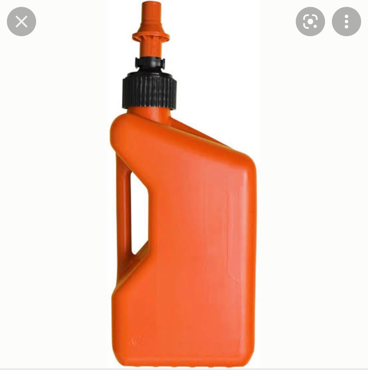
On 17/01/2022 at 10:57 PM, APenNameAndThatA said:
You can get jerry cans that you tip upside down, and the weight of the fuel opens the tap. Very little spilling. This one is called a Tough Jug. I can’t vouch for the quality. I was looking for a pic because people were mentioning jerry cans and electric pumps. This is an alternative to a normal jerry can. One advantage of this is that the aircraft supports the weight of the jerry can while the fuel flows.

Certainly reduces the chance of spillage.
At near $100 you could have an electric pump.
Resembles the 10L 2/ can I have for our chainsaws etc
If only 10L its going to take a lot of cans to do the job
If 20L still have the problem of lifting (especially for high wings)
Not so good on (near) vertical fill points
Wouldn't want to carry fuel in the aircraft - likely to vent at altitude and may not be 100% spill proof if falls over
-
1
-
-
On 18/01/2022 at 7:09 AM, walrus said:
I have finally formed a plan for refuelling my high wing aircraft:
1. Insert AN6 dry break socket in fuel line between tank and shutoff valve.
2. Bosch 044 electric pump or equivalent with suitable fuel hose attached.
3 Dry break plugs on either end of hoses, also a 100 micron or less filter with dry break coupling.
‘’To refuel - insert suction end with filter into jerry can and pump.
‘’To defuel reverse direction of hoses and suck.
‘’Pump can be powered either from jumper pack or aircraft battery.
No mess, reduced fuel spillage opportunities. I have big vents on the tanks that will handle an overfilling incident.
No step ladders, climbing, balancing, funnels, etc.
What is not to like?
Sounds great.
Questions/thoughts
All those couplings must cost a bit
With all those connections, the potential for a fuel leak has risen significantly
The pump cost $200-400 is way over the top for an on ground transfer pump - get a Chines knock off for under $100
The flow rate of the pump isn't bad - you will take about 4 minutes to deliver 20L (under ideal conditions)
What sort of pump is the Bosh? - if its centrifugal its ability to self prime will be marginal and any "head" will have a dramatic impact on flow rate
You may want to think twice about the filter - it will cause a significant restriction, slowing fuel delivery
If refuelling from a drum/can, a rigid tube/spike on one end of the pump is the safest and easiest way to go.
-
1
-
-
No need for the hing
-
I did this (not a Savannah) by taping two lairs of HD cling fil to my cowling, over the are where I wanted the inspiration door to be. Then taped the outline of the door to the film. Built up several layers of composite within making tape (doesnt matter if you cover tape). Let cure. Mark & very carefully cut cowling. Cut contoured plate to exact size of hole. You now have a perfectly fitting panel that you can paint & secure in several different ways (be sure to use a system that will not catch air blast/slip stream if left/comes open in flight.)
-
Guday Ralph,
I am also an Ag Scientist - just short of 30 years with NSW Ag before in "voluntary" redundancy - such is life.
Recently passed my Class 2 medical what a P--- in the Donkey! Belatedly realised I could just have gone for the Class 2B (or whatever name ) to hold on to my PPL privileges. Cheaper and way less fuss.
-
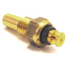
On 02/12/2021 at 2:57 PM, skippydiesel said:
I have a heap of these - they work very well indeed (no need for ugly amateur solutions).
These are applicable to anyone using the Rotax style oil/coolant temperature sensors with a disc shaped connector. Anyone interested????
-
On 15/01/2022 at 6:47 AM, Bruce Tuncks said:
My experience with the SK jabiru was that the cooling ducts were not good enough to begin with but after hours of tweaking, they were much better. I still, to this day, watch the temps on climbout and do the things skippy says if needed on a hot day. Keeping the CHT's under 160 C is the aim.
I fully agree with the idea of experimentation. That is, proper experimentation backed up by proper measurements. Tufting and photos qualify here, not that I have ever done this but others have and their work was very helpful. And getting other opinions sure helps too, I spent a lot of time playing with the inlet side of the carby, trying to even out the egt's, before I was told on this site that the real action needed to be on the downstream side.
I am not sure how you would "tuft" the inside of a cowl - light & cameras would be needed and you might still need to do area pressure readings. Sounds like a wind tunnel job to me. Way beyond my meager resources
Fingers crossed, my intention to go for a combined "nostril" (cool air in) area, equal or slightly larger, than the coolant radiator face area.
My hope, this will deliver a bit more air than required for extended taxi/holding and climb out.
If it works out this may mean too much cool air at cruise & in winter - solution a pilot operated cowl flap.
If I to go this rout, the flap will be (due to location limitations) on the inside of the cowling (rather than traditional exit) and may only cover a portion of the radiator (determined by using temporary tape).
On the other hand , if temps too high, I have the option of enlarging "nostrils" or more likely adding a small (possibly NACA) duct, directing air onto oil cooler and at the same time providing a larger volume of air to the coolant radiator.
This will be an exciting (possibly frustrating) project, that will commence when I have a airworthy cowling/aircraft, in about 2 -3 months
-
1
-
-
It might be wise to look at the cost V effect/benefit of a CS.
Cost; Likely to be in the $10 k area -$2k +6k depending on supplier.
Effect/benefit; As mentioned mainly in take off performance, with some top end benefit.
-
1
-
-
3 hours ago, turboplanner said:
RFguy I know you like to do theoretical sums, so I'd recommend you think about my deadly serious post.
To what/which post are you referring?
-
3 hours ago, spacesailor said:
RFguy
Number four ETHANOL !
If leaving any engine for extended periods, the ethanol will separate from it,s parent chemical, petrol or diesel,
Not good at all, l need to know how to over come this problem, with my car Unused for nearly a year now.
Could be Next year these unused vehicles, may explode the first time driveing .
My oil is two years out of date, but no kilometers driven, do l change the oil per p o h,. ( 12 month ).
spacesailor
Check engine/filters for nesting creatures & remove, charge or replace battery - inflate tyres to correct pressure (consider replacement ASAP) - drain as much old fuel as you can - refill with fresh - start engine - drive to get engine up to even running temperature (minimum 20 minutes longer better) - drain engine oil and replace with fresh - also replace break fluid at earliest opportunity.
-
KGW Just one point on "shelf life" of 98 RON - the reserch has consistently shown that 98 is good for at least 6 months IN A SEALED CONTAINER filled to 75 % capacity or above . Also a good dollop of fresh 98, added to your possibly stale fuel (in tank) will restore almost all the good attributes lost due to volatilisation. So instead of filling your tank, when you return from a days flying, consider doing so just befor you fly next.
-
1
-
-
Forgot to address; There will be lots of differing opinions on these two topic (fuel cans & pumps previously extensively addressed)
"How do you get it the airfield? Is it a headache carrying jerry cans and trying not to spill fuel?
I started by using pre loved metal 20 litre oil drums - Pros; no cost, as already had them. Cons; awkward, dont seal well/ fumes and spilt fuel, get rusty bottoms (potential contamination).
I then moved to the plastic replacements to above - Pros; no cost as already had them, no rust/water contamination worries and they seal well (no spills or fuel degradation). Cons; they are quite delicate and dont take even slightly rough handling or sun warmed fuel pressure (split).
Next - Bunnings Aero Space $18 plastic fuel containers - Pros; Cost effective compared with flashier 4x4 types and traditional metal jerries. Seal well. being jerry shaped easy to strap down for transport. Cons; non really except for the commentary from the (metal jerry) traditionalists and an undersized filler/pour point.
" trying not to spill fuel?"
Don't know if I have coved this in the above or if you re refiring to transferring fuel to aircraft tank.
Transferring fuel from transport container to aircraft tank ,is a pain no matter high/low wing - As a maturing person, I found lifting 20 L containers into position and then trying to achieve a no spill pour to be quite taxing and sometimes unpleasant due to spilling fuel on myself.
I resolved to purchase an efficient 12V petrol transfer pump. It turns out there are a legion of diesel/kero transfer pumps out there but very few petrol rated ones. What there is tend to be bulky and very expensive. Solution build my own- One Chinese copy ($70) of a high volume/flow Holly positive displacement vain pump, a length of good quality automotive twin (-/+) cable, length of single auto cable (plus alligator clip) for ground, 2 small Anderson plugs, some black polly fittings and a suitable length of automotive fuel hose I have a pump which will deliver 20 litres in about 3 minutes. Uses the aircraft battery (through an Anderson plug) Comes apart for storing in the aircraft and has so far been perfectly reliable. I use a home made filter funnel for all fuel entering the aircraft tanks.
Note: manual petrol compatible fuel transfer pumps are also bulky, expensive and difficult to work on your own (need a slave)
-
1
-
 1
1
-
-
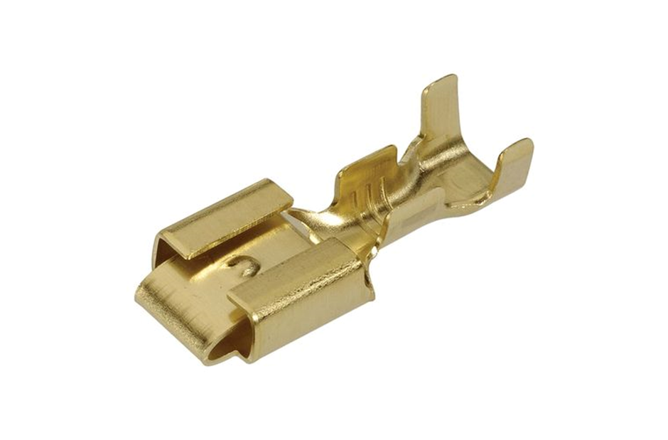
1 hour ago, Geoff_H said:
...................... With a professional crimp tool!
You probably know - the correct crimping tools come in either AWG sizes or additional parts to accommodate different wire /terminal dimensions. The best deal that I found was Toledo at about $70 (from memory they do about 3-4 sizes)- still expensive for tow cables but just a tad cheaper than the & thousand plus dollars for a MIL Spec pair.
-
I have been using 98RON in my Rotax 912ULS for the past 10 years/500 hrs or so .
Have , in desperation used AvGas on one or two occasions (no discernible benefit).
On one occasion, again in desperation, resorted to 95RON from a no name brand - definite reduction in performance.
Have used 95RON from brand suppliers without ill effect or noticeable change in performance.
My reasons for using 98RON are;
- Given the widespread belief that ULP can be subject to adulteration during transport/storage, I figure that 98 will give me somewhere between 95 & 98 RON in my tank. This is preferable (to me) for the potential that 95 to be lower than the Rotax specified minimum RON (see above comment)
- In general 98RON is more widely available than 95RON
If possible purchase from an established brand supplier, with a high fuel turn over (for freshness)
-
2
-
9 hours ago, walrus said:
Rotax has a current Service instruction - SI-912 i-001 that details what is required. Anything else, including web posts is hearsay and possibly out of date or just plain wrong - and that comes from a certified Rotax engineer.
Rotax requires a minimum RON of 95. up to 10% ethanol is permissible. The SI list various complying national specifications.
Avgas reduces your maintenance periods and possibly increases fuel consumption (mogas has about 3% more energy).
Vapor lock is a known issue that is a matter for the airframe manufacturer, not Rotax.
I use brand name UL95 fuel from a busy service station.
Ends.
Picky I know BUT ;
"............up to 10% ethanol is permissible." Is true as far as the engine itself goes but does not necessarily cover on board fuel tank & delivery systems - check with your aircraft maker and or use common sense - all components must be ethanol compatible/tolerant to use E10 or any other ethanol blend.
"Vapor lock is a known issue that is a matter for the airframe manufacturer, not Rotax" - Again correct however as far as I know no airframe manufacturer has been able to overcome the inherent design of Rotax 9 series (carburettor) engines in that all fuel to carburettors must pass over the engine and is therefore potentially subject to heating and subsequent "vapour lock" particularly after engine shut down and/or extended holding/taxi time.
-
1
-
1
-
-
8 minutes ago, RFguy said:
you'll have to build it and fly it....or at least taxi it !
With a little luck, 2-3 months to have it painted and Mk1 cowling fitted & ready to go.
My Rotax 912 ULS aircraft design idol ( Robin Austin) suggested that exit air control, was probably more important, in his World Record aircraft VH- SGS, than inlet sizing. (http://www.worldrecordplane.com/)
-
1 hour ago, RFguy said:
yeah but it had as you said : " The coolant radiator, located front lower cowling, with dedicated opening. "
the opening was a good size, to be sure, but I bet not quite big enough to climb slow at WOT all day in a australian summer. but you dont need to I guess/
My guess is they got clever with the airflow in the cowling for the oil cooler- they knew the airflow, modelled it etc.
They may have "modelled it" but the fact remains, no special ducting to ensure cool air flow AND (belatedly realised) much smaller coolant radiator & oil cooler, than the Sonex I now have.
I am not smart enough the debate the physics of the matter (nor do I dispute your maths) BUT I never had a overheating problem (overcooling in winter months, yes) and yet the system, fitted to the Zephyr, is the epitome of the "KISS" principal itself.
My point is; the Rotax cooling system, that I am used to is, with a little common sense (management) applied, more than capable of dealing with an Australian summer - who wants to do a full power, max, extended time, climb on a 45 degree day ? Not me!
There is little point is specifying the cooling system for a situation which is unlikely to occur ("climb slow at WOT all day in a australian summer"). If it did, the pilot will always be able to apply mitigation (heat reduction) strategies such as - lower the nose (when at safe altitude) reduce power (less heat) and increase speed (more cooling air) and/or "step" climb . The best strategy of all - manage your TO to coincide with the cooler times of the day.
At this stage (cowling design) my biggest concern is cooling on the ground (extended taxi/holding) - will my system have sufficient airflow to keep temperatures within safe limits ? AND if TO after extended holding, on a warm day, will the already heat soaked engine have sufficient cooling during initial climb out to safe altitude? No need to answear as I suspect all of this will be determined by flight testing.
-
1
-
-
13 minutes ago, PommyRick said:
The primary benefit of having CAPS is that it gives you one more option to choose from should the worst happen, so of course it would always be preferable to fly an aircraft with one.
Fair comment/opinion, if you are flying an aircraft with similar performance (stall in particular) to the Cirrus and at night (options to "out land" may not be visible).
For RAA class aircraft with 45 knot stall, strictly day VFR ,its seem in my opinion to be gross overkill - added expense, loss of space/pay load (yes I know there may be a small gross TO weight allowance) for very little (not none) safety improvement BUT if it makes you feel good, go for it.
-
1
-
-
Forgotten the name of the person who PM'd me regarding a Dynon A of A/pitot head - may be you didn't get my response in the affirmative - try [email protected]
-
4 hours ago, Ian said:
Radiator cowling design is an extremely difficult subject and most of the work in this space was done in WW2. If you can find someone with a moderately good solutions it's probably the right one unless you have a lot of time to burn.
What most people don't realize is that a really good radiator design can develop thrust (meredith effect), the P52 radiator design is probably is probably one of the best, however this really only works when your airspeed is pretty high. However at the very least good cooling duct design can be advantageous if you have the space available.
The lower the airspeed through the radiator the lower the drag. Aerodynamic drag increases as the cube or the airspeed and drag due to the radiator size increases at the square of airspeed. So you can exchange radiator area for reduced drag.
The duct should be divergent/convergent and there are maximum rates of change in the angles which can be used. Also the duct needs to be slightly larger post radiator as energy has been added to the airstream.
I am in complete agreement with your theory, however could you be over stating this for a RAA class aircraft?
My last aircraft, an ATEC Zephyr, had no internal (cowling) ducting. General air through two “front “nostrils”. The coolant radiator, located front lower cowling, with dedicated opening. The oil cooler, lower right, fixed to firewall, just to one side of exit air opening (no special opening or ducting). I made and used a “fixed” cowl lap for winter (below 250C) operations. Never had a heating problem in 500 hrs/10 years.
-
2 hours ago, facthunter said:
Same area as the radiator will be too big. The air is impeded when it goes through the radiator matrix and slows down considerably. Even fly screens slow wind a lot.. Thicker and finer are the worst offending radiators. At that point the pressure drop must be considerable to get flow. It takes quite a decent sized belt and fan to pull air through a radiator. Have a look at road graders and they are diesel and more efficient.. The prop would impart a swirl to the air in that region and the openings should take account of that. Nev
Not the same area as the radiator (which would be huge) the same area as the radiators frontal opening. Velocity/volume would be what can be delivered by the big fan up front on the ground (aircraft stationery/taxying) and ten by relativly high speed air when flying (plus fan). No point in trying to force more air through the radiator than it can cope with or thet will exceed relativly efficient transfer of heat from one medium to another (copper fins to air).

MOGAS and UL98 in Rotax 912 - Real experiences?
in AUS/NZ General Discussion
Posted
Well I have been using my Holly (Chines knock off) for about 6 years now. Anderson plug Under panel,direct to "ship" battery, pump up to 70L in one filling, and so far not a problem.