

skippydiesel
-
Posts
7,611 -
Joined
-
Last visited
-
Days Won
73
Content Type
Profiles
Forums
Gallery
Downloads
Blogs
Events
Store
Aircraft
Resources
Tutorials
Articles
Classifieds
Movies
Books
Community Map
Quizzes
Videos Directory
Posts posted by skippydiesel
-
-
Great topic - to carry it a little further -. I did the initial fuel tank calibrations, on my Sonex, during our winter months (day temps max 15C). Recently rechecked - now summer temps (25-27C) - no way I could get the same volume of fuel into the tank. I always knew this but was still surprised at the change. I actually changed the metering to reflect the (lesser) summer volume, as this will be a more conservative fuel quantity than the reverse.
-
1 hour ago, IBob said:
Right, well according to this chart (which agrees with your #35 being just over 0.5mm) what you are looking for is #15 or #20:
https://www.allensperformance.co.uk/carb-kit/jet-size-chart/Wow! Great work IBob.
The #15 looks the goods (closest to IBob's 0.35mm) , assuming that the aperture size alone dictates the flow rate.
Will place my order this evening.
-
8 minutes ago, facthunter said:
Anything modern will be injected and electronic. Can't you check this with just a boost pump pressure and the motor stopped? There would be a full range of AMAL main jets available forever as long as old english bikes exist. They are on flow rate. Obviously that will vary with pressure differential. The "pull" on the fuel depends on the engines mass airflow and Venturi size .Too big a venturi and the jet size becomes larger and insensitive and the carburetter hard to tune, Nev
Fuel return line Nev - not a carburetor.
I guess the relative performance of each jet could be judged using just the boost pump but being a simple sort of person, I would prefer to subject the jet to the actual environment that I expect it to perform in.
As for pressure - all I can tell you is, the existing Rotax jet 35 returns 7+l/hr at the pressure developed by the standard Rotax diaphragm pump. My Dynon tells me, during pre TO checks, that it ranges from 4.5-5.5 psi depending if boosted by auxiliary pump. This pressure drops to below 2 psi during TO/Climb. Whatever jet I replace, the existing one with, will be measured under the same pressure regime.
-
Thanks for the very kind offer Bob - my fuel manifold/distributor is a custom job. I need a smaller/lower flow, Mikuni jet to replace the 0.53mm one I have.
That your system uses (about) 0.35mm gives me a factual "goal" to aim for - just need to find out which Mikuni type VM 22/120 jet(s) might be in the ball park.
-
I am hoping a Forum member has experience with (hotting) engines and has played around with carburettor jetting. This helpful person may be able to suggest which Mikuni type VM 22/120 jet(s) might give me the 3-4L/hr I seek - if flow rate too low, could then use the Nev method .
-
14 minutes ago, facthunter said:
It's easy to open up one that's a bit too small. Use a sewing needle with a flat ground on one side as a reamer. The flow rate is easy to check over a shorter period than one hour. I'd start with a .012" Hole Nev
True I could just purchase a Mikuni #10 (the lowest flow rate)? and adjust it to my own liking - prefer to get the correct or slightly undersized jet & modify.
FYI Mikuni do not publish jet ID dimension's and all their jet numbers relate to flow(also unpublished) at a ? pressure (presumably a standard).
As for "check over a shorter period" why when I can fly (real world test) for or over, several hours, then divide the Hobbs time by the contents of the container/tank.
-
2 hours ago, pluessy said:
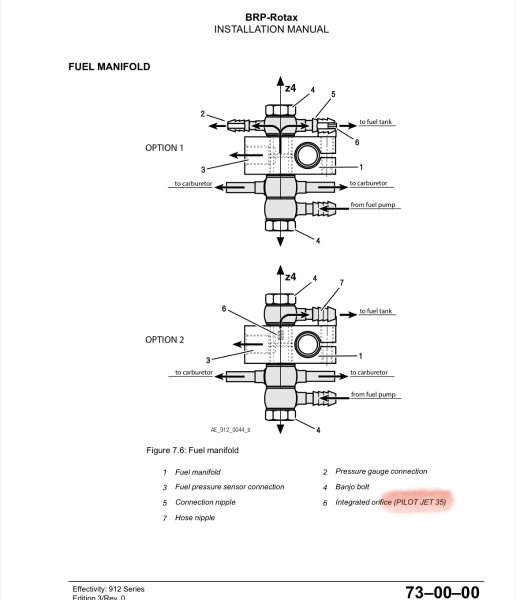
no need, the #35 (0.35mm) jet has been documented by Rotax and mentioned a few times in this thread.

Unless Rotax have changed their part, the jet supplied to me on the 25/01/2023, PN 963820, "Pilot Jet 35" actually measures .53mm (ID) definitely not 0.35 mm
The Rotax fuel line return restrictor jet is almost certainly a Mikuni type VM 22/120 #35 - Why ? The design/shape, dimensions & number of holes, matches the Rotax part.
Further the Mikuni numbers relate to flow (not a specific jet ID). Unfortuatly I have been unable to find the flow data.
Are you able to assist?
-
What no past/present hot rodders ??
Fluid dynamic oficiendo's armature/professional???
-
Some more information:
The Rotax fuel lune return restrictor jet is almost certainly a Mikuni VM 22/120 #35.
These slow idle jets come is a wide range of flow rates # 10 - #140
I would like to reduce my flow rate of 7+l/hr down to 3-4 L/hr . Anyone on the Forum able to sugest which # jet is most likly to meet my needs?
(Mikuni person cant/wont help)
-
2 hours ago, RocketShip said:
Have made a start of the Static Cling that I got from Autobarn. Getting it around the curvature of the Canopy is the difficult part.
I have made a template using light cardboard. Will then cut the Static Cling from that. Trying to do it so I don't get any overlap on the curvature.
Easier said then done.
Its not easy - depending on curvature, you may have to cut a slot or three.
Once done will stay in place as long as you want it to - easy to remove.
Make sure you put the reflective side up.
Good luck
Just read CC's post - no bubbles if you have purchased the perforated static film.
-
 1
1
-
 1
1
-
-
1 hour ago, rgmwa said:
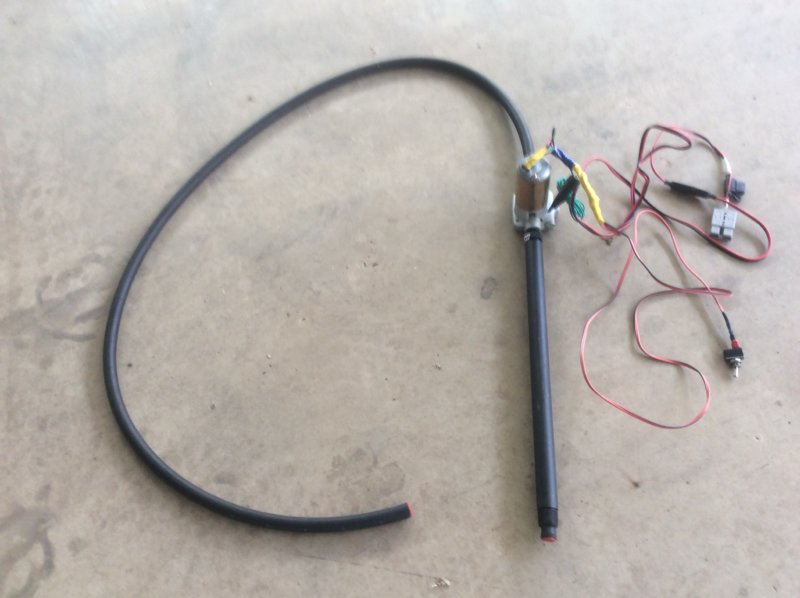
I'm always cautious about electrical terminals, wiring and batteries around fuel. The pumps in the above two examples are directly above the open fuel container outlet where I imagine there would be a fair bit of evaporation going on, especially in hot weather. Do you two aviators see any particular risk with those setups or am I being overly concerned?
Yes there is an increased risk (ref Onetrack above).
I, and I think Blue, have come up with a refueling system that is not much more risky than decanting (static spark could still bring you undone). So its up to the individual to assess & manage the risk according to their standards. I would urge all pilots to read & understand Onetrack's list of potential ignition sources and decide for themselves how they will manage the risk they have accepted, so as to minimise the chance of a fuel fire.
I have weighed the risk of fire against the increasing risk to my aging back, the chances of spillage with its cariogenic potential, ignition, smell damage to clothing & aircraft surfaces.
My fuel pump is designed for petrol transfer in high consumption engines - as such, I hope it is well sealed against fuel/air entry
I ;
Have a dedicated earth/ground lead on my pump for connecting to the aircraft.
My fuel containers are in contact with the ground/concrete
Refuel, for preference, in the open air , if not, with hanger doors wide open
Make all my electrical connections before opening fuel container/tanks (I use Anderson plug connectors)
Have my delivery nozzle well down in the filter funnel (rich air fuel mixture)
Hold my on/off switch in the hand away from the fuel delivery
The switch itself is well insulated/covered, minimising potential fuel vapour entry
I have used figure 8 cable for my pump electrical system but on recommendation from RFGuy will change to two core double insulated
My electrical system has an in line fuse that I hope will shut the electrical supply down in the event of a short.
-
4
-
1
-
-
Congratulations Blue - your set up is almost perfect.
Uses almost all the same components as mine, with one significant acceptation - mine is designed to be portable ie can be taken on away trips.
-
2
-
-
1 hour ago, RFguy said:
just a point of order here you must price in the ladder to be apples for apples
How do the fill -underside setups work for a 737 ?
😀 True! but then height enhancement devise will be required for most high wing refueling/ fuel remaining check situations.
The challenge in doing away with the ladder or similar, blows my mind - some sort of extended device for removing/refitting the fuel cap, a mirror/camera for seeing where the dip stick needs to inserted and reading of the same..................!
-
1
-
-
On 21/01/2023 at 5:59 PM, Flightrite said:
At $85 bucks I’ll stick to the simplest design known to mankind, jiggle syphon👍
Agreed IF you are able to get the supply container higher than the delivery point.
I also agree with those who have found hoisting 20 L containers has become a bit of a strain, down sizing to 10L containers (various delivery options) BUT at the end of the day using a relatively light weight, low cost, compact pump, to efficiently deliver fuel to high/low wing tanks, without strain, fear of spillage, must surely be the ultimate goal.
-
2
-
-
Some options;
https://autobarn.com.au/ab/Autobarn-Category/Brands/Streetwize/STATIC-CLING-SUNSHADE-BLACK/p/PR18387
https://www.autobarn.net/static-cling-sunshade.html
https://www.bunnings.com.au/perma-child-safety-static-cling-car-shade-2-pack_p0348261
http://www.haigh.com.au/products/interior-accessories/sun-shades/static-sun-shades-detail
-
2
-
-
Back to sunshades - This topic has been discussed befor, on this Forum, - my ingestion then & now is a $15 shear of reflective static cling, that can be purchased from most auto accessory stores (got mine from Autobarn). It cheap, does the job and allows for some see through advisability and is light weight. Cut to size & shape ( to avoid wrinkles be sure to accommodate curvature of canopy )
-
2
-
-
Mk2 works well BUT as you experienced builder/pilots will know, an adjustment to one control surface will impact on another;
Now have a left wing drop - did have the left flap up as far as it would go, to correct an earlier right wing drop. Have now turned left wing flap down by 1/2 turn of control rod end. Hope to test fly, in the cool of the early morning, tomorrow.-
1
-
1
-
-
Test report - Trim worked a little too well. Have removed it , cut in 1/2. Will re fit and try again.
-
2
-
1
-
-
If the Beverlys so great what about the last remaining Shorts Belfast - last seen/could still be there, Cairns Airport. Its owner, an Australian, about to recommission her.
I forgot to mention - 50 were order for the RAF - the new British Prim minister, M Thatcher, cut the order down to 10 and purchased American C130's instead - who ever said politics made sense?
-
1
-
-
I am not against the idea, just want to give the little trim tab a go first.
In fact when we have completed all the adjustments (for now) I will probably fit her with a pilot adjustable aileron bungee/spring, to counter the weight of a passenger. I had this on my last aircraft - worked a treat - its a one way system ie it will only work to "lift" the right wing.
-
1 hour ago, facthunter said:
An adjustable spring bias will do it. Replaces what your hand does. Jabiru and DH82 pitch are done that way (and probably many others. ).
Thanks Nev - Yes I did think of that system but felt that at slow speeds (landing, etc ) the fixed trim tab would likely be not as effective, where a spring system would be constant (unless there was a a pilot trim adjust) and unhelpful at low air speed/taxying. I have always felt that these little planes should be subject to the KISS principal, unfortunately the urge to get more sophisticated/complex is overwhelming.
-
1
-
-
19 minutes ago, Kiwi said:
Get some of the 6mm door molding trim about 75mm long and stick it in the thrust line on the side you are pushing the rudder. If to much try a shorter piece, not enough make it longer.
Neat idea!
Might be a bit heavy if a long 40mm strip is required.
The aluminium molding/extrusion I have already stuck (double sided tape & white gap tape )in place but not tested, is curve ( . I toyed with he idea of fixing it convex out (as per your door molding) but opted in the end to try concave out . Its 200x30x1.5mm, secured at the mid point on the rudder trailing edge.
-
1
-
-
This aircraft is in its early test flying stage - my son & I are slowly working through all its (mainly) small "teething" problems.
Changing the engine alignment, is no small fix and I am not even sure that it is possible without a major rebuild.
The aircraft, a Sonex Legacy (A), has been meticulously built according to Mr Monnet's plans - there has been some builder "customisation" but engine alignment was not one of them.
The need for right rudder, in cruise, is quite slight/subtle with the "ball" almost aligning without it - a small helper trim tab may be all that is needed.
I have temporarily fixed (double sided tape) a small aluminium extrusion, to the rudder trailing edge , at the mid point - the next test flight will give me some idea of its effectiveness or not.
-
8 hours ago, aro said:
How did you measure the return flow rate? Timed flow into a container?
8 hours ago, aro said:Did it the most accurate real world way I could - Directed return line fuel into its own collection tank. Flew the aircraft (several TO/Landing & cruise over several hours). Drained & measured fuel from dedicated tank. Fuel quantity divided by Hobbs hours.
Just rechecked my notes - the actual flow rate is 7.6L/hr (Hobbs)
-
1
-
.JPG.f144c486276dcce483382e6b3338c73d.JPG)
.JPG.9e697178499f18e441341a89319773fb.JPG)
.JPG.1ced1132a1ebb5edd4a4f5c58b7ed3d4.JPG)
Tie downs
in AUS/NZ General Discussion
Posted
Based on very little experience, a large dollop of common sense and observation of several types being used at" fly in's"
All the "stake" types:
The screw in's;
Claw types:
Home made;
All systems are best used at an angle to aircraft tie down point and the minimum of 3 should be placed so as to appose each other ie you don't want the lift forces acting vertically on the ground tie.
Have yet to see a system that comes close to meeting all possible soil conditions.
For my money the light weight, HT metal screw in's, with sizeable flights and a large lever "eye" that can accommodate a piece of wooden dowel as a handle, are the best compromise.
Just because its sold through an aircraft accessory store or has an aeroplane on the front cover, is no reason to pay ridiculous extra dollars.