
Old Koreelah
-
Posts
6,237 -
Joined
-
Last visited
-
Days Won
55
Content Type
Profiles
Forums
Gallery
Downloads
Blogs
Events
Store
Aircraft
Resources
Tutorials
Articles
Classifieds
Movies
Books
Community Map
Quizzes
Videos Directory
Posts posted by Old Koreelah
-
-
Thanks, DP, that's interesting and makes sense having the outer sleeve taper away from the inner one.Bolt or rivet, you need a sliding fit for a good mechanical join. This means, no slop, but then no pressure needed to push the 2 together either. The sizes you are giving leave way too much play to form a sound joint and therefore the rounding or tapering the inner surfaces of the outer tube are a mute point at this stage. For what it's worth, I would opt for a gradual arc bringing the wall thickness to about half it's original size and being about 10/15 times as long as it's reduction size. Does that make sense? eg. a 0.5mm reduction in wall thickness over a length of 5 to 7.5 mm. Just make sure there are no hard edges at the start point inside the tube. This will become a wear point if any.[ATTACH=full]14989[/ATTACH] -
Yes Pud, that sound right. With hinge-points offset like a Jab, the flap is rotated thru about 37° and also pushed and pulled thru an arc by two actuating rods inside the fuselage.Would I be correct in surmising that the stresses on the leading edge of your flaps here would not be that great, and therefore the stress line you speak of OK would be minimal? I imagine most forces acting on this component would be torsional, therefore the fixings (bolts and/or rivets?) would be taking most of the load, and that in shear.Pud -
Good point, Rick. A famous test pilot is reputed to have explained his survival in a long career by saying that he was never surprised when the engine stopped; he was always surprised when it didn't.The question on everyones lips should be what am I going to do and how will I react when the engine does stop...It doesn't matter what engine you fly they are all engineered and everything and anything engineered can and will break, eventually...
Rick-p
-
 2
2
-
-
Thanks DP, I learned both metric and imperial in a little rural NSW school in the 1950's- must have had a forward-thinking teacher!I hope I'm wrong but I've calculated a 3.5(179)mm gap all round your inner tube. I'd suggest you look for something around 0.5mmAlthough I was raised in the UK with Imperial measurements, it is a damn sight easier to use the metric system.I already have the two tubes, and the larger one fits pretty snugly over the long inner tube, with just enough space for some epoxy metal glue. I have not been able to upload my pix, so a description: If the ends of the overlapping sleeve are straight, then I fear a stress line could be established. If I "scallop" the ends of the outer joining sleeve tube to a continuous S-shape it should distribute stresses over a larger area. Any comments welcome.
-
Lyle, you sure they're the correct sizes? 0.35" is a pretty thick wall thickness. Almost 10mm, and there's going to be a pretty big clearance twix the 2 tubes.
Sorry for the typo DP, the tubes are 2024T3; the inner is 1.5'' dia. with 0.035" wall; the outer is 1+7/8" with 0.049" wall.
(Gawd I don't understand these archaic measurements; give me a few microns any day...)
-
Thanks, DP, the tubes are 2024T3; the inner is 1.5'' dia. with 0.035" wall; the outer is 1+7/8" with 0.35" wall.Lyle, to make an informed decision we need to know the tube diameters and wall thicknesses. -
Good top see the sense of humour survived as well!Least we didn't have to eat dugs drink urine and write help in our blood like the guy over seas , eprib much better if needed -
- Click "Settings" in the top right of the site header (Can't see this; I must be in the wrong page, or do pages look different on a Mac?
- Click "General Setting" in the left menu bar on that page that is displayed
- Scroll down to the bottom of the displayed page and with the option of "Enhanced Attachment Uploading:" click "Enhanced Attachment Uploading off"
- Click the "Save Changes" button on the right of the page
3. Adding An Attachment To Your Post
When creating a new thread or post you will see the "compose" form that has a Title field, Formatting Toolbar, Entry box for typing, Smilies (click one to add it into your post
 ) and more.
In the Formatting Toolbar you will see a Paper Clip with up/down arrows: Not found either.
- Click "Settings" in the top right of the site header (Can't see this; I must be in the wrong page, or do pages look different on a Mac?
-
Thanks Pete for the attempt to help, but I only use Macs, which normally handle graphic with ease. I cropped the JPEG to 25KB so it should load in an instant. I have not had this problem with other sites.Try resizing the photo. Right click on the photo you want to upload, click on edit, click on resize in the paint program, click on pixals, and change to about 640 x 480 for a portrait photo or the other way round for a landscape orientated photo. When you close that program say yes to saving the photo. It will now be useable to upload into the forum. -
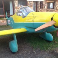
Nice camera, but tell us more about the aircraft, especially the pre-rotator.[medio=full]82[/medio] -
Yenn I agree with your assessment and watch this issue with interest. My little Jodel has similar issues; The only time I can really use full power is on climb. Cruise needs to be no more than 2800 rpm; any more nudges my VNE.With a finer pitch I would have less chance of preventing cylinder glazing. The revs would be high but the pressures less. A coarser prop would help with the glazing problem, but climb would suffer and I would have to be even more careful of over revving. -
Sure doesn't look much like the movie versions of Great War pilots nonchalantly taking off to fight the Hun.
Looks like the biggest danger they faced was from their own aircraft.
-
I can't help you, but when you get the numbers, ensure it's for the correct engine. I was sent a plate which was too large for my 2.2L, so I presume it was meant for a 3.3L.Does anybody knows the Jabiru propeller holes pattern? (the diameters of center holes, diameter of bolt holes and the bolt holes pattern on PCD)ThanksHarris:puzzled:
-
Sorry OME, I followed the tutorial which seems to refer to a previous incarnation of this page setup, but it failed to load.Lyle,Your picture did not come up. Please post again with the photo as an attachment.OME
-
[quote="rgmwa, post: 176269"]Haven't seen the photo, but understand that you want to avoid a sharp transition in stiffness at the end of the sleeve. Best would probably be a long taper but as the material is thin, the taper would be very short. My suggestion, and that's all it is, would be to consider cutting a series of equally spaced V's (like deep serrations - maybe 20mm deep?) with rounded and deburred ends and `valleys'. and with an internal angle of around 20-30deg. This will transition the stiffness over the 20mm length.
rgmwa
Thanks for the feedback. I followed the tutorial but my pic did not load. Damn computers. I could modify my "scollops" so they are like your deep V serrations, as long as all edges are smoothly curved.
-
Because, like the Irishman, I want be sure, to be sure, to be sure. If my rivet work is dodgy, then a metal epoxy bond will ensure nothing works loose over years of use. (If I need to dismantle epoxy joins, heat will do it)Is this tube joining the 2 flaps and also acting a an actuator? If it is I would assume the main loads would be torsional, and the rivets would take that load. Why use glue, which would make repair in the event of damage much harder to do? -
I seek advice about connecting two aircraft grade aluminium tubes which will serve as the leading edge of my flaps. For simplicity and added strength, I am making the flaps in one piece, so the connected tubes will be 4.5m long. At the centre the overlapping sleeve, about 500mm long, will be both glued and riveted over the tubes it is joining. It will also take most of the torque loads from the flap actuating lever.
I have the material ready to do the job and feel that it may be wise to avoid a rigid strong point at the overlap, in case it leads to stress fractures. The two obvious solutions are shown in the attached picture; to "bevel" the very thin outer tube at the join, or (my preference) to "scollop" the edge with smooth curves, so that a single stress line cannot develop. Any suggestions?
Lyle
[ATTACH]14970[/ATTACH]
-
"
Tell them that the Qantas pilots who saved the A380 were once trainee pilots in a little airfield somewhere, and the pilots at the little airfield might save their lives one day. If we don't train pilots, we will have to import pilots trained in India and China, like doctors."A great idea, Mazda.
-
Best argument I've seen for shaking up traditional education.
-
1
-
-
Nice, short landing, W68!
-
Good on you for getting the discussion underway, Carol.
At one previous NatFly we could book our services as volunteers on the day. A roster allowed breaks from whatever jobs people would do. Perhaps the board could nominate a co-ordination who could post a list of the sorts of jobs, and skills needed, so that we can plan our contribution. The Co-ord might then end up with a list of helpers available well before the event.
-
"I've got a feeling I've heard that James Packer flies something like a Quiksilver or similar up at their property "Ellerston" north of Scone - could be wrong though"
When our recent Ops Manager was my instructor at YSCN, he was also doing maintenance on a pair of rag and tube aircraft that he said were from the Packer property.
Lyle
-
Whoops! Good to see the Ejector seat work as specified. My fantasy job, landing on a carrier; like simultaneously having a car accident and an orgasm...
We're told that, due to the powerlag, the jet pilot has open the throttle as he nears touchdown, in case the hook-up fails.
-
Thank you John. Its good to have a well-presented explanation of the board's roles. Many members may be surprised at the tedious but essential work our board does to ensure our freedoms. Hopefully our new reps can form a team to work harmoniously for the future of our fine organisation. I'm sure members appreciate the enormous and unrewarded efforts of our leaders.
Lyle
-
2
-
 ) and more.
Engine failure
in AUS/NZ General Discussion
Posted
Proper preparation of the repair, including scarfing the join at the correct angle, are a big part of the repair.