Leaderboard


Popular Content
Showing content with the highest reputation since 07/01/11 in Aircraft
-
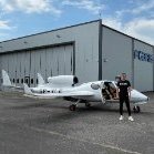
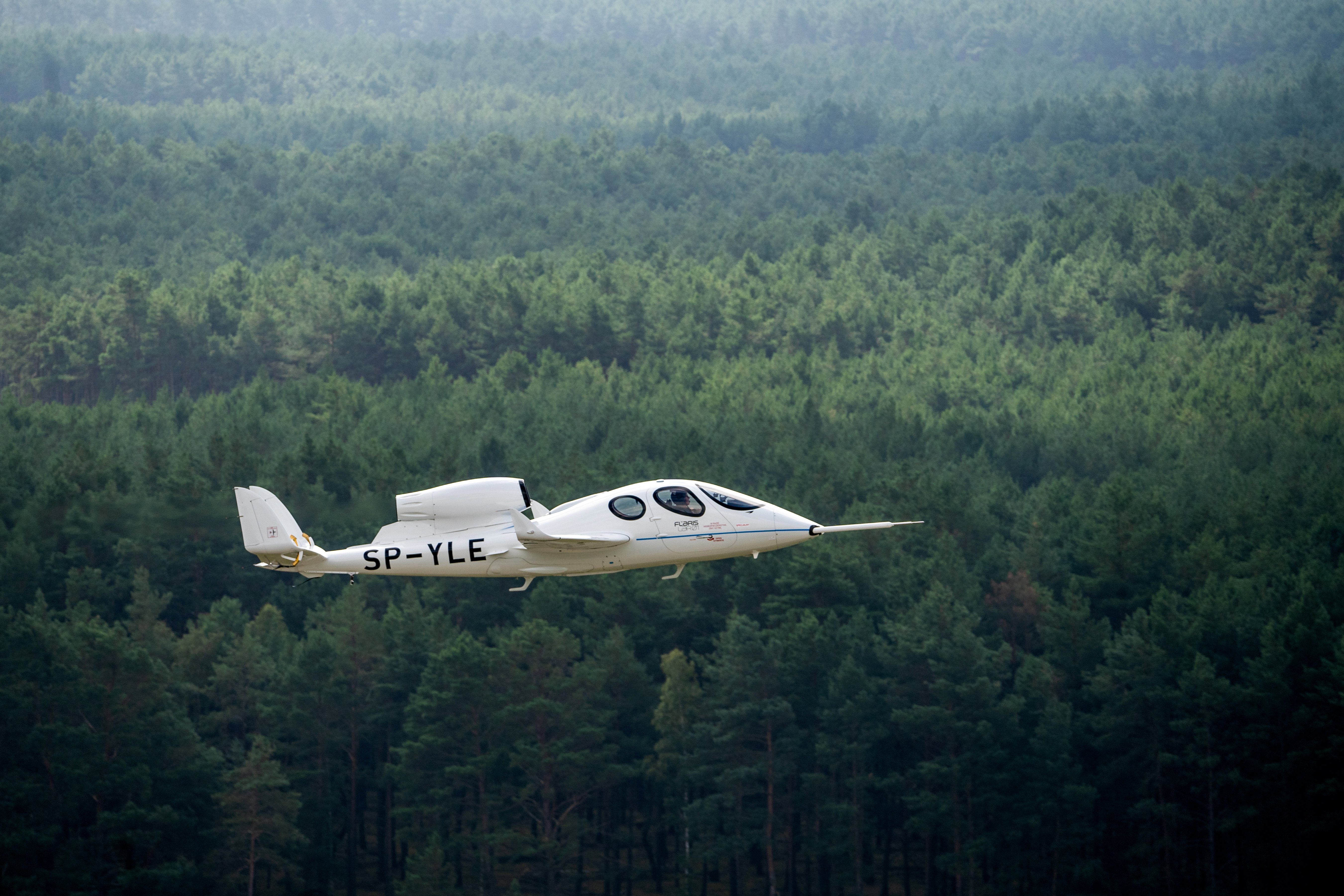 The Flaris LAR01 is a Polish five-seat very light jet intended for general aviation use. It is made largely of carbon fiber reinforced polymers and powered by a single turbojet engine – the production version of the LAR01 is to be powered by a single Williams FJ33-5A engine. The LAR01 is intended to be affordable and accessible to individual private owners. Proposed uses for it include air taxi operations, personal transport, emergency medical service and aerial surveillance , as well as its potential modification into an unmanned aerial vehicle (UAV). The LAR01 has been optimized for use by private pilots. Where possible, the cockpit is deliberately designed to mimic that of a traditional car. The designers intend to provide removable. Elliptical wings for the aircraft; this measure is to enable the type to be readily parked within typical garages; sections of the tailplane can be similarly detached for the same purpose. Fuel is housed within a tank mounted on the fuselage, deliberately avoiding the use of the wings for fuel storage. The LAR01 is also reported as being relatively easy to control. Various features for safety and convenience are to be incorporated into the LAR01's design. Unlike many jet-powered aircraft, it is claimed to be readily capable of being operable from unpaved runways and grass strips. For safety purposes, the LAR01 has been designed to use a ballistic rescue parachute system, a parachute being installed within the tail , which is intended to assist in the safe recovery of the aircraft. It can be equipped with various models of Garmin glass cockpit . An electric de-icing system is also fitted. Under 3 mln $ aircraft is forecast to have direct operating costs (fuel, maintenance and insurance) of $450 per hour and have a Garmin G600 TXi flight deck. It should cruise at 430 kn (796 km/h), have a range of 1,900 nm (3,519 km) with a MTOW of 1,500 kg (3,300 lb), and will be able to take off and land on grass airstrips and short runways of less than 250 m (820 ft).4 points
 -
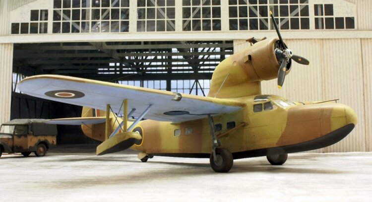 The Fairchild 91 (a.k.a. A-942) was a single-engine eight-passenger flying boat airliner developed in the United States in the mid-1930s. Fairchild designed the aircraft in response to a Pan American Airways request for a small flying boat to operate on their river routes along the Amazon and Yangtze. The result was a conventional high-wing cantilever monoplane with its radial engine mounted above the wing in a streamlined nacelle. Before construction of the prototype was complete, however, Pan American no longer required the aircraft to operate in China, and Fairchild optimised the design for the Brazilian tropics. After the first two aircraft were delivered, Pan American cancelled the remaining four aircraft of its order, as they no longer needed any for China, and the two aircraft were capable of handling the Amazon River. The sole A-942-B was specially built for the American Museum of Natural History and was used by naturalist Richard Archbold on his second expedition to Papua New Guinea in 1936–1937. The prototype was sold to the Spanish Republican Air Force, but the ship carrying it was captured by the Spanish Nationalists and was used by them until 1941. The A-942 bought by industrialist Garfield Wood was sold to the British American Ambulance Corps before being transferred to the RAF, who operated it in Egypt for air-sea rescue. One example was sold to the Imperial Japanese Naval Air Service for evaluation, but it was wrecked shortly after delivery, so a second example was purchased to replace it. Variants Fairchild 91 Baby Clipper Initial version built to Pan Am specifications for use on rivers, powered by a 750 hp (560 kW) Pratt & Whitney S2EG Hornet. Six built. Fairchild A-942-A Alternative designation for the Fairchild 91 Fairchild 91B Jungle Clipper Specially equipped for NYC Museum of Natural History, powered by a 760 hp (570 kW) Wright SGR-1820F-52 Cyclone. One built, NR777. Fairchild A-942-B Alternative designation for the Fairchild 91B. Fairchild XSOK-1 Proposed U.S. Navy scout; none built.[3] Fairchild LXF Two A-942Bs supplied to the Imperial Japanese Navy Air Service for evaluation.3 points
 -
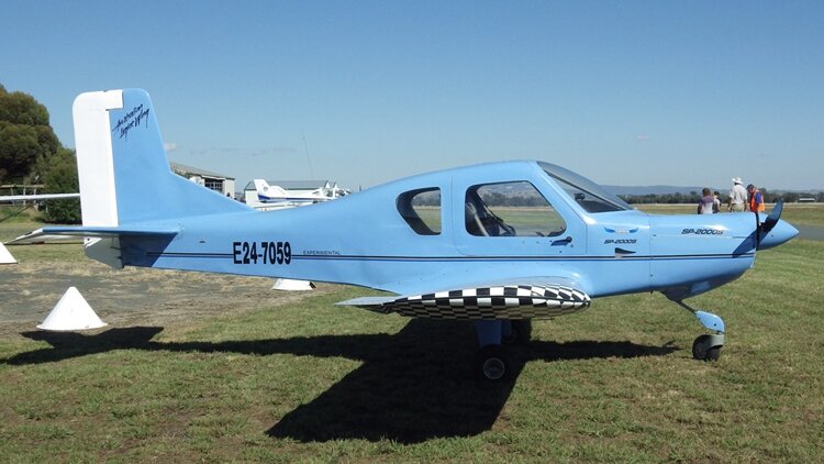 The Australian Lightwing SP-2000 Speed is an Australian light-sport aircraft, designed and produced by Australian Lightwing of Ballina, New South Wales. The aircraft is supplied as a kit for amateur construction or as a complete ready-to-fly-aircraft. The aircraft features a cantilever low-wing, a two-seats-in-side-by-side configuration enclosed cockpit, fixed tricycle landing gear or conventional landing gear and a single engine in tractor configuration. The aircraft fuselage is made from welded steel tubing covered in non-structural fibreglass. Its 8.7 m (28.5 ft) span wing is built from 6061-T6 aluminum covered in doped aircraft fabric and fibreglass. Standard engines available are the 100 hp (75 kW) Rotax 912ULS or the 120 hp (89 kW) Jabiru 3300 four-stroke powerplants. Cockpit access is via gull-winged doors on both sides. Wheel pants are usually fitted. The SP-2000 has been accepted by the US Federal Aviation Administration as a light-sport aircraft as the Outback 2. SP-2000 TD (Tail dragger variant)3 points
 -
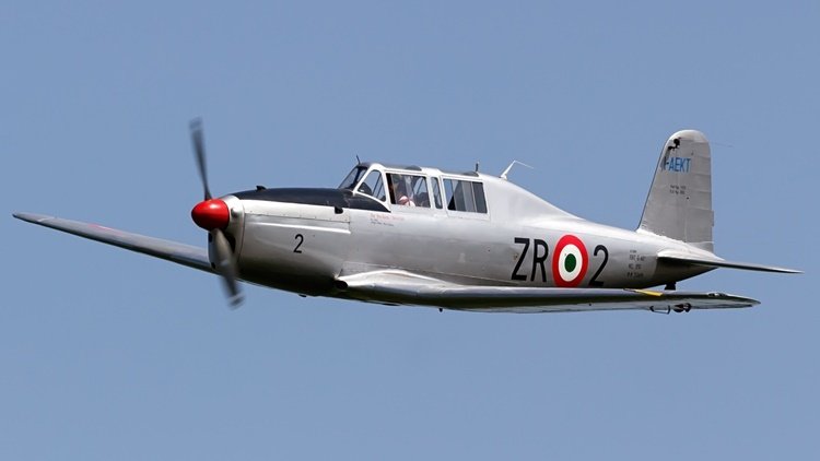 The G.46 was a conventional, low-wing monoplane with tailwheel undercarriage, the main units of which retracted inwards. The pilot and instructor sat in tandem under a long canopy. The first prototype, powered by a 205 hp (153 kW) Alfa Romeo 115-Ibis engine, made its maiden flight on 25 June 1947. Testing revealed excellent flying characteristics and suitability for aerobatics, and the type was ordered into production. Apart from the 150 ordered by the Aeronautica Militare, 70 aircraft were exported, to Austria, Argentina and Syria. Variants G.46-1B two-seater with Alfa Romeo 115bis engine, one prototype and initial production of 25 for the Italian Air Force. G.46-2B two-seater with de Havilland Gipsy Queen engine for the Argentine Air Force, 70 built with an additional 12 for the Syrian Air Force. G.46-3B two-seater with Alfa Romeo 115ter engine for the Italian Air Force, 25 built. G.46-4B two-seater with Alfa Romeo 115ter engine for the Italian Air Force, 55 built. G.46-5B two-seat navigation trainer (prototype only) G.46-4A single-seater with Alfa Romeo 115ter engine for the Italian Air Force, 35 built.3 points
 -
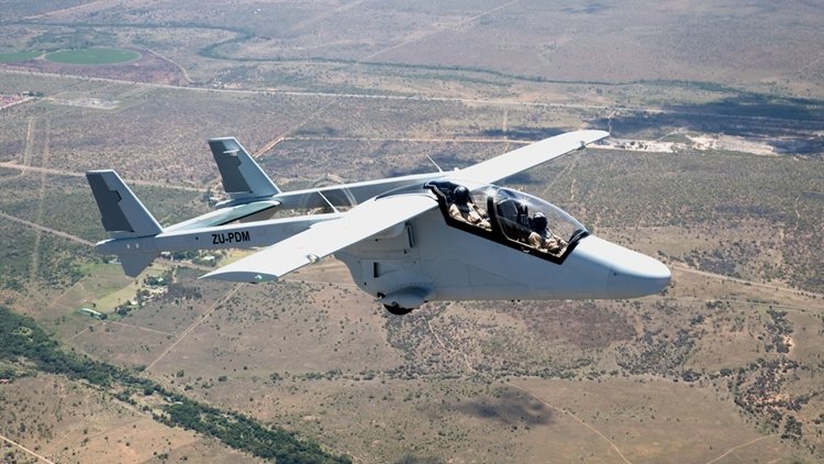 Mwari is a new light, multirole aircraft being developed by Paramount Group for armed forces across the globe. It is a military variant of the Advanced High Performance Reconnaissance Light Aircraft (AHRLAC). The Mwari project was unveiled in May 2016. Paramount and Boeing made a cooperation agreement in September 2014 for collaborating on specific projects to be implemented in future. The agreement was extended in May 2016 to jointly develop an advanced mission system for the Mwari aircraft. . The cost-effective Mwari multirole aircraft can be deployed in border patrol, counter insurgency missions, forward air control, forward airdrop and resupply, armed reconnaissance, and electronic intelligence (ELINT) and communication intelligence (COMINT) missions. Other mission capabilities will include internal security, disaster management and maritime patrol. Incorporating a twin-boom design, the Mwari aircraft will feature airframe constructed using meal and composite materials. The longitudinal booms at empennage feature a pair of vertical stabilisers joined by a horizontal stabiliser. The high-wing design will improve visibility for the crew, while allowing operations from unprepared airfields. The modular design will also support the integration of different mission systems for a range of military operations. The aircraft will have a length of 10.5m, wing span of 12m and a height of 4m. The maximum take-off weight of the aircraft is 3,800kg and maximum payload capacity with full fuel load will be more than 800kg.3 points
 -
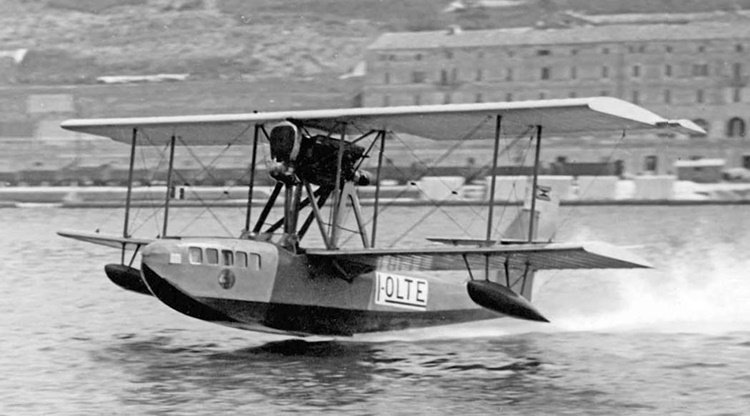 The CANT 10 was a flying boat airliner produced in Italy in the 1920s. It was a conventional biplane design with single-bay, unstaggered wings of equal span, having seating for four passengers within the hull, while the pilot sat in an open cockpit. The engine was mounted in pusher configuration in the interplane gap. CANT 10 flying boats were used by Società Italiana Servizi Aerei for over a decade, linking destinations in the Adriatic Sea. Two CANT 10ters were used by a company called TAXI AEREI in Buenos Aires, operating flights from the River Plate. One of them was lost in an accident and the other one was bought by the Paraguayan government for the Naval Aviation in 1929; it was used as a transport during the Chaco War and was withdrawn from use in 1933. A total of 18 CANT 10's were built.3 points
 -
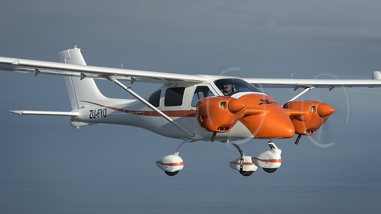 Len and Les Alford of Jabiru Aircraft Southern Africa are the South African dealers for Jabiru. They approached Jabiru in 2012 suggesting there was a market for a twin engine Jabiru in Africa. They explained that parts of Africa are best flown over at a great heights, and the prevalence of wild animals and AK47s tends to make flyers nervous about outfield landings. The conclusion…two engines would be nice. The project was always intended to be a joint development and aimed at the South African market. Jabiru had conjured the concept of a twin for some time but could not face up to the complexity generated by hanging the engines off the wings. This would have meant going back to basics on wing structure and all the difficulties of fire-proofing the wings, etc. Another physical difficulty was the engine pods completely obstructed the entry and exit points to the cabin. These considerations gave birth to the idea of mounting the engines on a short canard mounted on the firewall. Some quick calculations on the weight and balance weren’t too frightening and Jabiru was able to get the propellers quite close together to reduce the amount of asymmetric thrust on one engine. The issue of opening the doors against the engine pods was resolved and the design evolved from there. Jabiru’s John Farmer got to work making a streamlined nose for a J430 airplane and the two engine pods. Jabiru’s engineer, Tom Ferguson, was given the task of testing the supporting structure for the engines. As usual, most of the structure was built in composite with aluminum connections to the engines. The firewall structure of the J430 is unchanged and the nose wheel remains in its normal position. This is a relatively simple bolt-on modification. When the structure was finished and the molds were complete, the project was shipped to South Africa where the airplane was completed into a flying prototype. Jabiru is considering releasing the aircraft as a kit for Australian and U.S. builders, and in other countries that accept the experimental category. It’s also possible that it could be released as a conversion to existing experimental J430s in Australia.3 points
 -
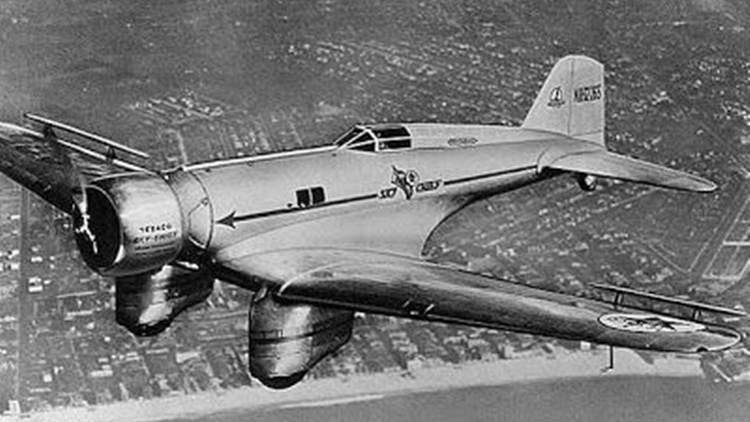 The Northrop Gamma was a single-engine all-metal monoplane cargo aircraft used in the 1930s. Towards the end of its service life, it was developed into the A-17 light bomber. The Gamma was a further development of the successful Northrop Alpha and shared its predecessor's aerodynamic innovations with wing fillets and multicellular stressed-skin wing construction. Like late Alphas, the fixed landing gear was covered in distinctive aerodynamic spats, and the aircraft introduced a fully enclosed cockpit. The Gamma saw fairly limited civilian service as mail planes with Trans World Airlines but had an illustrious career as a flying laboratory and record-breaking aircraft. The US military found the design sufficiently interesting to encourage Northrop to develop it into what eventually became the Northrop A-17 light attack aircraft. Military versions of the Gamma saw combat with Chinese and Spanish Republican air forces. Twenty Five Gamma 2Es were assembled in China from components provided by Northrop; these were deployed in various attack missions during the early stages of the Second Sino-Japanese War, particular against Imperial Japanese naval assets. In the morning of 11 November 1937, three Chinese Air Force Northrop 2ECs of the 2nd BG, 14th Squadron led by Capt. Yu attacked the IJN fleet aircraft carrier Kaga off the Ma'anshan Islands; the bombs fell wide into Kaga's wake, and the Chinese Gammas were pursued and intercepted by three A5Ms of Kaga's combat air patrol led by flight leader Jirō Chōno, shooting down two (Gammas no. 1405 of Sung I-Ching and Li Xi-Yong, and no. 1402 of Peng Te-Ming and Li Huan-Chieh) while Yu managed to escape into the clouds and return his damaged Gamma to base. On June 2, 1933 Frank Hawks flew his Gamma 2A "Sky Chief" from Los Angeles to New York in a record 13 hours, 26 minutes, and 15 seconds. In 1935, Howard Hughes improved on this time in his modified Gamma 2G making the west-east transcontinental run in 9 hours, 26 minutes, and 10 seconds. The most famous Gamma was the Polar Star. The aircraft was carried via ship and offloaded onto the pack ice in the Ross Sea during Lincoln Ellsworth's 1934 expedition to Antarctica. The Gamma was almost lost when the ice underneath it broke, and had to be returned to the United States for repairs. Polar Star's second assignment to Antarctica in September 1934 was also futile — a connecting rod broke and the aircraft had to be returned yet again for repairs. On January 3, 1935, Ellsworth and pilot Bernt Balchen finally flew over Antarctica. On November 23, 1935, Ellsworth and Canadian pilot Herbert Hollick-Kenyon attempted the world's first trans-Antarctic flight from Dundee Island in the Weddell Sea to Little America. The crew made four stops during their journey, in the process becoming the first people ever to visit Western Antarctica. During one stop, a blizzard completely packed the fuselage with snow which took a day to clear out. On December 5, after traveling over 2,400 miles (3,865 km) the aircraft ran out of fuel just 25 miles (40 km) short of the goal. The intrepid crew took six days to travel the remainder of the journey and stayed in the abandoned Richard E. Byrd camp until being found by the Discovery II research vessel on January 15, 1936. Polar Star was later recovered and donated to the Smithsonian National Air and Space Museum. For details of the 14 variants, click here. Specifications below are for the Gamma 2D variant. Gamma 2A Gamma 2E Gamma 2G Gamm 2J Northrop A-17 derivative3 points
 -
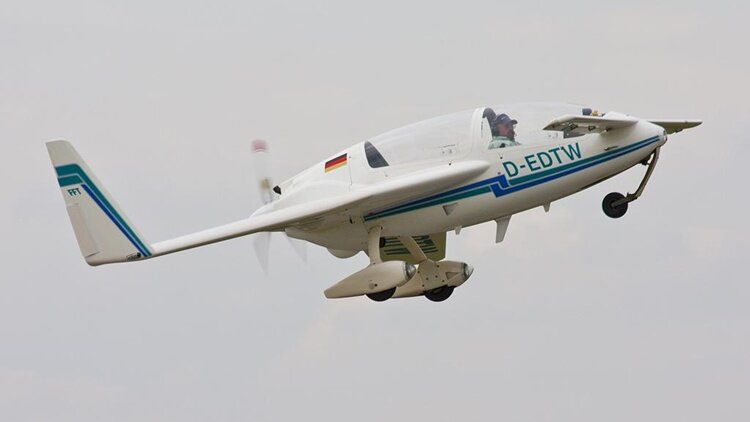 The Gyroflug SC 01 Speed Canard is an unconventional sports plane produced in Germany in the 1980s and 1990s. Inspired by the Rutan VariEze, the Speed Canard was an all-new design created without input from Rutan. Like the VariEze, the Speed Canard is a canard-configured mid-wing monoplane with wingtip fins that incorporate rudders. The two-seat tandem cockpit and canopy design were derived from Grob Twin Astir sailplane, and the nosewheel of the tricycle undercarriage is retractable. Construction throughout is of composite materials, and when the design attained German certification in 1983, it became the first composite canard design to achieve certification anywhere in the world. An interesting feature of the control system is that the twin rudders operate independently, allowing both rudders to be deflected outwards simultaneously, cancelling each other's yaw, but acting as airbrakes. In 1987, the development of a four-seat version was announced as the E 401, but was abandoned soon thereafter. In late 1988 Gyroflug partnered with Litton Industries using Gyroflug Speed Canard as for Litton's Advanced Tactical Surveillance System.2 points
 -
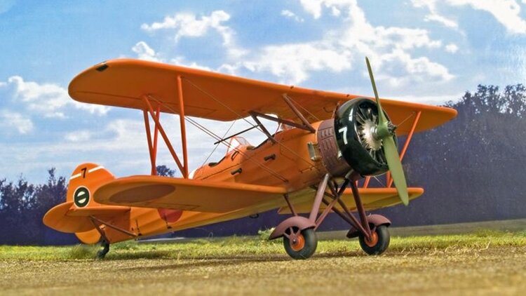 The Tachikawa Ki-9 (九五式一型練習機, Kyūgo-shiki ichigata renshuki) was an intermediate training aircraft of the Imperial Japanese Army Air Force built by Tachikawa Aircraft Company Ltd in the 1930s. It was known to the Allies under the nickname of "Spruce" during World War II. This aircraft was mistakenly identified as a Tatchikawa by the British. The Ki-9 was a two-seat, unequal wingspan biplane design. Tachikawa originally planned to use the same basic airframe for both basic training and intermediate training, differentiating the two models by the use of different engines. The prototype Ki-9 flew on 7 January 1935, powered by a 261 kW (350 hp) nine-cylinder Hitachi Ha-13a radial engine. The second prototype was identical, and the third prototype was powered by a 112 hp (80 kW) Nakajima NZ seven-cylinder radial engine. The third prototype exhibited stability problems due to a center of gravity issue, and, as a result, the primary trainer model was abandoned and the Ki-9 was developed only for the intermediate trainer. Tachikawa subsequently developed the Ki-17 for the primary trainer role. The first production aircraft were delivered in 1935. The Ki-9 was introduced to service as the Army Type 95-1 Medium Grade Trainer Model A under the former aircraft naming nomenclature system. The first version had a complex, split-axle landing gear with fairings over the top of the wheels. In 1939, this was modified and simplified, the fuselage slightly shortened, and the total weight reduced. The resulting Army Type 95-1 Model B or Ki-9-kai had improved maneuverability and flight characteristics. This version was quickly superseded by the Army Type 95-1 Model C, or Ki-9-otsu, in full production. Both versions were used widely for blind-flying training with a folding hood over the rear cockpit, and several were modified with a glazed canopy over the rear cockpit for use as a staff officer transport plane. Some were pressed into service for use as "special attack" (kamikaze in American terminology) aircraft in the closing days of the war, fitted with either a 100 kg anti-ship bomb, an oil drum filled with explosives, or fuel in the rear cockpit. Production by Tachikawa totaled 2,395 aircraft, ending in 1942. At least another 220 Ki-9s were constructed by Tokyo Gasu Denki (also known as Gasuden) from 1943 to 1945. The Ki-9 was also flown in wartime by Japanese satellite countries and postwar by the fledgling government of Indonesia and captured units by the Republic of China. Variants Ki-9 (Army Type 95-1 Medium Grade Trainer Model A): Initial version two-seat intermediate trainer aircraft. Ki-9-ko (Army Type 95-1 Medium Grade Trainer Model B): Improved version. Ki-9-otsu (Army Type 95-1 Medium Grade Trainer Model C): Standard production version.2 points
 -
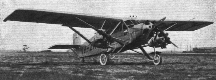
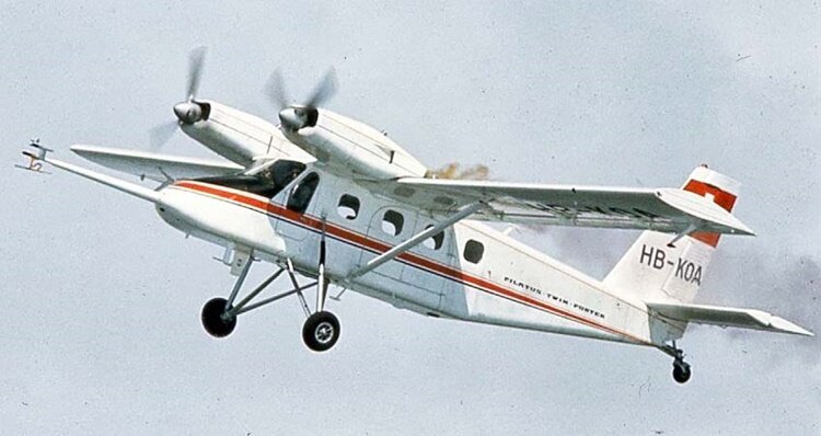 The Pilatus PC-8D Twin Porter was a Swiss ten-seat light transport built by Pilatus Aircraft. The type did not go into production and only one was built. Work on the Twin Porter started in 1966, it was a modified Pilatus PC-6 high-wing monoplane with the nose-mounted engine removed and two 290 hp Lycoming IO-540-GIB engines mounted on the wing leading edges.The prototype first flew on 28 November 1967. Only one aircraft was built as flight testing was halted in 1969.2 points
 -
 The Lasco Lascondor (also frequently known by the misspelling "Lasconder") was a 1930s Australian 8-seat passenger and mail carrier aircraft built by the Larkin Aircraft Supply Company (Lasco) at Coode Island, Victoria. It is claimed to be the first multi-engined aircraft designed and built in the Southern Hemisphere. Development of the Lascondor began in June 1928, concurrently with the company's Lascoter; the two aircraft had 90% commonality of structural parts. Like the Lascoter the Lascondor was a high-wing monoplane with a tubular steel structure, featuring a tailwheel undercarriage and a fully enclosed cabin for the passengers and the pilot. A major change was the Lascondor's three Armstrong Siddeley Mongoose engines instead of the Lascoter's single more powerful Siddeley Puma engine. The Lascondor also had greater fuel capacity and a slightly longer fuselage with a redesigned cabin to accommodate an extra row of seats. In addition, while the Lascoter had two sets of flying controls in the cockpit the Lascondor had only one to allow for another passenger seat, giving an overall capacity of seven passengers and one pilot. The only available photo of the Lascondor.2 points
 -
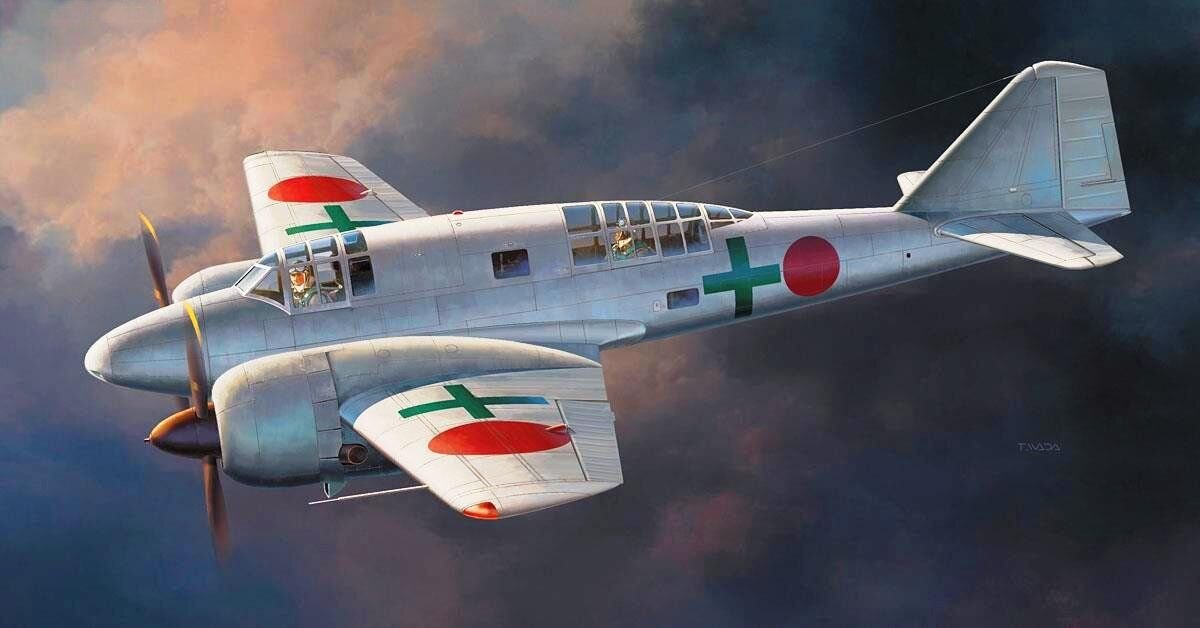 The Mitsubishi Ki-46 was a twin-engine reconnaissance aircraft that was used by the Imperial Japanese Army in World War II. Its Army Shiki designation was Type 100 Command Reconnaissance Aircraft (一〇〇式司令部偵察機); the Allied brevity code name was "Dinah". On 12 December 1937, the Imperial Japanese Army Air Force issued a specification to Mitsubishi for a long-range strategic reconnaissance aircraft to replace the Mitsubishi Ki-15. The specification demanded an endurance of six hours and sufficient speed to evade interception by any fighter in existence or development, but otherwise did not constrain the design by a team led by Tomio Kubo and Jojo Hattori. The resulting design was a twin-engined, low-winged monoplane with a retractable tailwheel undercarriage. It had a small diameter oval fuselage which accommodated a crew of two, with the pilot and observer situated in individual cockpits separated by a large fuel tank. Further fuel tanks were situated in the thin wings both inboard and outboard of the engines, giving a total fuel capacity of 1,490 L (328 imperial gallons). The engines, two Mitsubishi Ha-26s, were housed in close fitting cowlings developed by the Aeronautical Research Institute of the Tokyo Imperial University to reduce drag and improve pilot view. The first prototype aircraft, with the designation Ki-46, flew in November 1939 from the Mitsubishi factory at Kakamigahara, Gifu, north of Nagoya.[3] Tests showed that the Ki-46 was underpowered, and slower than required, only reaching 540 km/h (336 mph) rather than the specified 600 km/h (373 mph). Otherwise, the aircraft tests were successful. As the type was still faster than the Army's latest fighter, the Nakajima Ki-43, as well as the Navy's new A6M2, an initial production batch was ordered as the Army Type 100 Command Reconnaissance Plane Model 1 (Ki-41-I). To solve the performance problems, Mitsubishi fitted Ha-102 engines, which were Ha-26s fitted with a two-speed supercharger, while increasing fuel capacity and reducing empty weight. This version, designated Ki-46-II, first flew in March 1941. It met the speed requirements of the original specification, and was ordered into full-scale production, with deliveries starting in July. Although at first the Ki-46 proved almost immune from interception, the Imperial Japanese Army Air Force realised that improved Allied fighters such as the Supermarine Spitfire and P-38 Lightning could challenge this superiority, and in July 1942, it instructed Mitsubishi to produce a further improved version, the Ki-46-III. This had more powerful, fuel-injected Mitsubishi Ha-112 engines, and a redesigned nose, with a fuel tank ahead of the pilot and a new canopy, smoothly faired from the extreme nose of the aircraft, eliminating the "step" of the earlier versions. The single defensive machine gun of the earlier aircraft was omitted not long into the production run. The new version first flew in December 1942, demonstrating significantly higher speed 630 km/h (391 mph) at 6,000 m (19,700 ft). The performance of the Ki-46-III even proved superior to that of the aircraft intended to replace it (the Tachikawa Ki-70), which as a result did not enter production.[8] During operational testing in March 1944, it was discovered that replacing the engines' single exhaust collector ring with individual pipes provided extra thrust and an increase in top speed to 642 km/h (399 mph). In an attempt to yet further improve the altitude performance of the Ki-46, two prototypes were fitted with exhaust driven turbosupercharged Ha-112-II-Ru engines. This version first flew in February 1944, but only two prototypes were built. Mitsubishi factories made a total of 1,742 examples of all versions (34 x Ki-46-I, 1093 x Ki-46-II, 613 x Ki-46-III, 4 x Ki-46-IV) from 1941 to 1944. For details of operational history and 18 variants, click here.2 points
 -
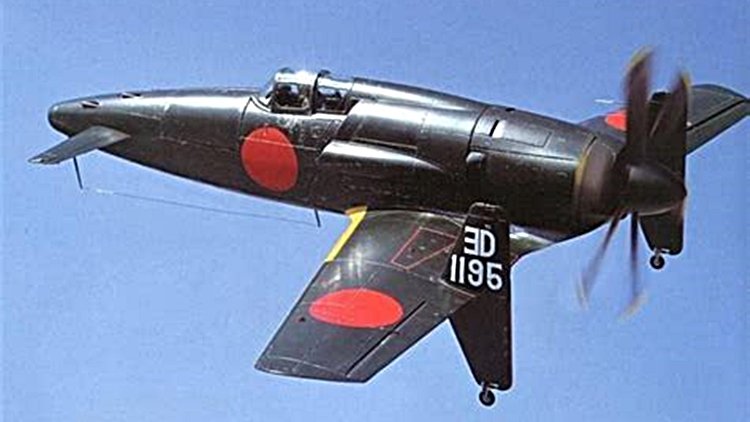 The Kyūshū J7W Shinden (震電, "Magnificent Lightning") is a World War II Japanese propeller-driven prototype fighter plane with wings at the rear of the fuselage, a nose-mounted canard, and a pusher engine. Developed by the Imperial Japanese Navy (IJN) as a short-range, land-based interceptor, the J7W was a response to Boeing B-29 Superfortress raids on the Japanese home islands. For interception missions, the J7W was to be armed with four forward-firing 30 mm type 5 cannons in the nose. The Shinden was expected to be a highly maneuverable interceptor, but only two prototypes were finished before the end of the war. A jet engine–powered version was considered, but never reached the drawing board. In the IJN designation system, "J" referred to land-based fighters and "W" to Watanabe Tekkōjo, the company that oversaw the initial design. The idea of a canard-based design originated with Lieutenant Commander Masayoshi Tsuruno, of the technical staff of the IJN in early 1943. Tsuruno believed the design could easily be retrofitted with a turbojet, when suitable engines became available. His ideas were worked out by the First Naval Air Technical Arsenal (Dai-Ichi Kaigun Koku Gijitsusho), which designed three gliders designated Yokosuka MXY6, featuring canards. These were built by Chigasaki Seizo K. K. and one was later fitted with a 22 hp Semi 11 (Ha-90) 4-cylinder air-cooled engine. The feasibility of the canard design was proven by both the powered and unpowered versions of the MXY6 by the end of 1943, and the Navy were so impressed by the flight testing, they instructed the Kyushu Aircraft Company to design a canard interceptor around Tsuruno's concept. Kyushu was chosen because both its design team and production facilities were relatively unburdened, and Tsuruno was chosen to lead a team from Dai-Ichi Kaigun Koku Gijitsusho to aid Kyushu's design works. The construction of the first two prototypes started in earnest by June 1944, stress calculations were finished by January 1945, and the first prototype was completed in April 1945. The 2,130 hp Mitsubishi MK9D (Ha-43) radial engine and its supercharger were installed behind the cockpit and drove a six-bladed propeller via an extension shaft. Engine cooling was to be provided by long, narrow, obliquely mounted intakes on the side of the fuselage. It was this configuration that caused cooling problems while running the engine while it was still on the ground. This, together with the unavailability of some equipment parts postponed the first flight of the Shinden. Even before the first prototype took to the air, the Navy ordered the J7W1 into production, with a quota of 30 Shinden a month given to Kyushu's Zasshonokuma factory and 120 from Nakajima's Handa plant. It was estimated some 1,086 Shinden could be produced between April 1946 and March 1947. On 3 August 1945, the prototype first flew, with Tsuruno at the controls, from Mushiroda Airfield. Two more short flights were made, a total of 45 minutes airborne, one each on the same days as the atomic bombings of Hiroshima and Nagasaki occurred, before the war's end. Flights were successful, but showed a marked torque pull to starboard (due to the powerful engine), some flutter of the propeller blades, and vibration in the extended drive shaft.2 points
 -
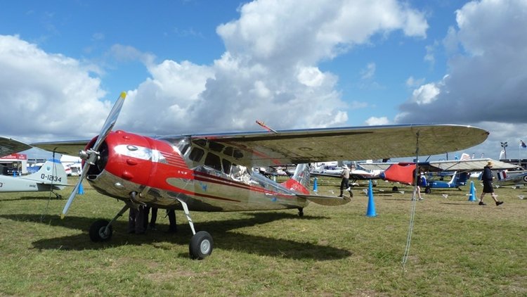 The Cessna 190 and 195 Businessliner are a family of light single radial engine powered, conventional landing gear equipped, general aviation aircraft which were manufactured by Cessna between 1947 and 1954. The 195 model was also used by the United States Air Force, United States Army, and Army National Guard as a light transport and utility aircraft under the designations LC-126/U-20. The Cessna 190 and 195 were Cessna's only postwar radial-engined aircraft. The first prototype flew in 1945, after the end of World War II and both the 190 and 195 entered production in 1947. The 195 was the first Cessna airplane to be completely constructed of aluminum and features a cantilever wing, similar to the pre-war Cessna 165 from which it is derived. The wing differs from later Cessna light aircraft in that it has a straight taper from root chord to tip chord and no dihedral. The airfoil employed is a NACA 2412, the same as used on the later Cessna 150, 172 and 182. The 190/195 fuselage is large in comparison to other Cessna models because the 42" diameter radial engine had to be accommodated in the nose. There are two rows of seats: two individual seats in the first row, with a comfortable space between them and up to three passengers can be accommodated on a bench seat in the second row. The 190/195 has flat sprung-steel landing gear legs derived from Cessna's purchase of the rights to Steve Wittman's Big X. Many have been equipped with swiveling crosswind landing gear which allows landing with up to 15 degrees of crab. While the crosswind gear simplifies the actual landing, it makes the aircraft difficult to handle on the ground. The 195 is equipped with a retractable step that extends when the cabin door is opened, although some have been modified to make the step a fixed unit. The aircraft was expensive to purchase and operate for private use and Cessna therefore marketed them mainly as a business aircraft under the name "Businessliner". The engines fitted to the 190 and 195 became well known for their oil consumption. The aircraft has a 5-US-gallon (19 L) oil tank, with 2 US gallons (7.6 L) the minimum for flight. Typical oil consumption with steel cylinder barrels is 2 US quarts (1.9 L) per hour. A factory-produced floatplane version was equipped with a triple tail for improved yaw stability. The Cessna 195 produces a cruise true airspeed of 148 knots (274 km/h) (170 MPH) on a fuel consumption of 16 US gallons (61 L) per hour. It can accommodate five people. Including the LC-126s, a total of 1180 190s and 195s were built. The 190 was originally introduced at a price of USD$12,750 in 1947 (equivalent to $173,978 in 2023). When production ended in 1954 the price had risen to USD$24,700 (equivalent to $280,239 in 2023) for the 195B. This compared to USD$3,495 for the Cessna 140 two seater of the same period. Variants The main difference between the 190 and the 195 models was the engine installed. 190 Powered by a Continental W670-23 engine of 240 hp (180 kW) and first certified on 1 July 1947. 195 (Specifications below) Powered by a Jacobs R-755A2 engine of 300 hp (225 kW) and first certified on 12 June 1947. 195A Powered by a Jacobs L-4MB (R-755-9) engine of 245 hp (184 kW) and first certified on 6 January 1950. 195B Powered by a Jacobs R-755B2 engine of 275 hp (206 kW) and first certified on 31 March 1952. It featured flaps increased in area by 50% over earlier models. LC-126A Military designation for the Cessna 195, five-seat communication aircraft for the US Army, it could be fitted with skis or floats, 15 built. LC-126B Similar aircraft to the LC-126 for Air National Guard use, five built. LC-126C Variant of the LC-126A for instrument training/liaison, 63 built. U-20B LC-126B redesignated by the USAF after 1962. U-20C LC-126C redesignated by the USAF after 1962.2 points
 -
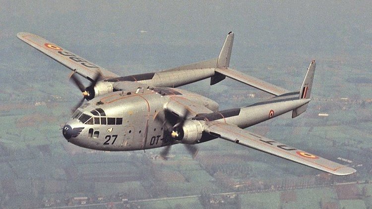 The Fairchild C-119 Flying Boxcar (Navy and Marine Corps designation R4Q) is an American military transport aircraft developed from the World War II-era Fairchild C-82 Packet, designed to carry cargo, personnel, litter patients, and mechanized equipment, and to drop cargo and troops by parachute. The first C-119 made its initial flight in November 1947, and by the time production ceased in 1955, 1,183 had been built. The Air Force C-119 and Navy R4Q was initially a redesign of the earlier C-82 Packet, built between 1945 and 1948. The Packet had provided limited service to the Air Force's Tactical Air Command and Military Air Transport Service before its design was found to have several serious problems. Though it continued in service until replaced, all of these were addressed in the C-119, which had its first test flight already in 1947. To improve pilot visibility, enlarge the cargo area, and streamline aerodynamics, the C-119 cockpit was moved forward to fit flush with the nose, rather than over the cargo compartment. The correspondingly longer fuselage resulted in more usable cargo space and larger loads than the C-82 could accommodate. The C-119 also got new engines, with 60% more power, four-bladed props to three, and a wider and stronger airframe. The first C-119 prototype (called the XC-82B) made its initial flight in November 1947, with deliveries of C-119Bs from Fairchild's Hagerstown, Maryland factory beginning in December 1949. In 1951, Henry J. Kaiser was awarded a contract to assemble additional C-119s at the Kaiser-Frazer automotive factory located in the former B-24 plant at Willow Run Airport in Belleville, Michigan. Initially, the Kaiser-built C-119F differed from the Fairchild aircraft by the use of Wright R-3350-85 Duplex Cyclone engines in place of Fairchild's use of the Pratt & Whitney R-4360 Wasp Major radial engine. Kaiser built 71 C-119s at Willow Run in 1952 and 1953 (AF Ser. No. 51-8098 to 51-8168) before converting the factory for a planned production of the Chase C-123 that never eventuated. The Kaiser sub-contract was frowned upon by Fairchild, and efforts were made through political channels to stop Kaiser's production, which may have proven successful. Following Kaiser's termination of C-119 production the contract for the C-123 was instead awarded to Fairchild. Most Kaiser-built aircraft were issued to the U.S. Marine Corps as R4Qs, with several later turned over to the South Vietnamese air force in the 1970s, a few others were later shipped to Belgium and Italy. The AC-119G Shadow gunship variant was fitted with four six-barrel 7.62 mm (0.300 in) NATO miniguns, armor plating, flare launchers, and night-capable infrared equipment. Like the AC-130 that replaced it, the AC-119 proved to be a potent weapon. The AC-119 was made more deadly by the introduction of the AC-119K Stinger version, which featured the addition of two General Electric M61 Vulcan 20 mm (0.79 in) cannon, improved avionics, and two underwing-mounted General Electric J85-GE-17 turbojet engines, adding nearly 6,000 lbf (27 kN) of thrust. Other major variants included the EC-119J, used for satellite tracking, and the YC-119H Skyvan prototype, with larger wings and tail. In civilian use, many C-119s feature the "Jet-Pack" modification, which incorporates a 3,400 lbf (15,000 N) Westinghouse J34 turbojet engine in a nacelle above the fuselage. For details of operational history and 21 variants, click here.2 points
 -
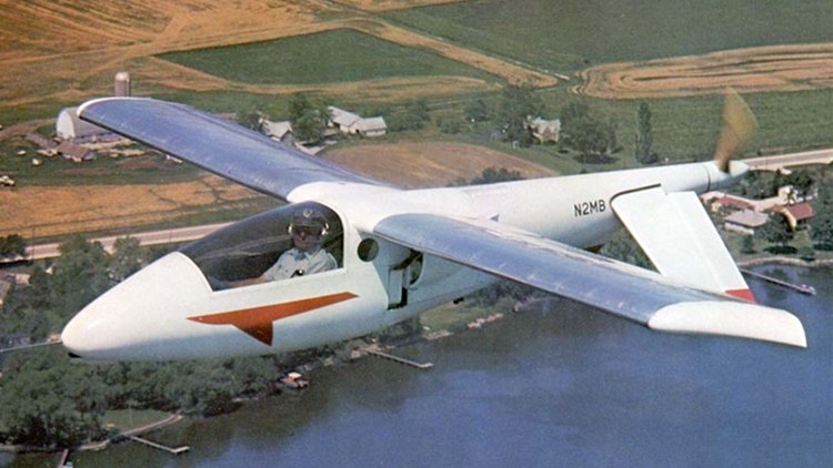 The Aerocar Mini-IMP (Independently Made Plane) is a light aircraft designed by Moulton Taylor and marketed for homebuilding by Aerocar International. It is a scaled-down derivative of his original Aerocar IMP design. A two-seat version called the Bullet was also built. The Mini-IMP follows the same unconventional layout as its larger predecessor, with a center mounted engine, long driveshaft to a tail propeller, and inverted-V rudder/elevators. The aircraft is available in the form of plans for amateur construction. Following Taylor's death, the plans and licensing for the Mini-IMP have been marketed by the Mini-IMP Aircraft Company of Weatherford, Texas. The aircraft features a cantilever high-wing, a single-seat enclosed cockpit, fixed or retractable tricycle landing gear or conventional landing gear and a single engine in pusher configuration. The aircraft is made from riveted aluminum sheet. Its 24.5 ft (7.5 m) span wing is mounted well behind the pilot and employs a NASA GA(PC)-1 airfoil. The engine is mounted behind the pilot's seat driving the propeller through an extension shaft. Engines used include the 60 to 100 hp (45 to 75 kW) Volkswagen air-cooled engine four-stroke. Taylor claimed the Mini-IMP was not an original design, but an updated version of the 1912 Edson Fessenden Gallaudet Bullet, a design that was capable of 110 mph in the earliest days of flight. In the late 1970s inquiries were made concerning a military version of the Mini-IMP, skinned with Kevlar, armed with two 7.62-millimeter machine guns, and with room in the baggage compartment for a considerable quantity of ammunition. Nothing came of the proposal.2 points
 -
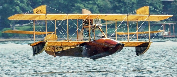 (No to be confused with the Curtiss SOC Seagull of WW2) The Curtiss Seagull was a civil variant of the Curtiss MF flying boat trainer produced from 1918, the civil aircraft having a 119 kw (160 hp) Curtiss C.6 six-cylinder in-line engine in place of the V-8 unit in the military variants. The MF was one of a long line of flying boats produced for the US services following the entry of the United States into World War I, when flying boats were required for patrolling coastal waters to prevent German submarine operations. Two examples of the Seagull came to Australia. Seagull G-AUCV (c/ n MF.419/28) was registered in 1921. It left Double Bay, Sydney, NSW on 13 March 1921 and made an epic flight to and from Tasmania, this being described as the First Aerial Reconnaissance in Australia, the pilot being Capt Andrew Lang(said to be shot down by the Red Baron during World War I, the operation being financed and promoted by Lebbeus Hordern. Cameras were carried on board in order that aerial photographs could be taken of the coastline. The auxiliary yacht ‘Acielle’ accompanied the expedition and acted as a tender for the Seagull. The flight was made in short stages, the first night being at the Shoalhaven River, near Nowra, NSW, thence to Jervis Bay, Moruya, down the coast to Eden and Marlo where the Victorian Premier, Mr Lawson, was met. Later he was taken for a flight over the area. Stops were made and local flights were made with passengers. From Welshpool it flew to Lady Barren and then across the Tasman, landing on the Tamar River close to Cataract Gorge. The return flight commenced on 19 June and the aircraft arrived at Double Bay on 4 July 1921. The bottom photo below shows the aircraft on the Tamar River. For more details of these aircraft click here.2 points
 -
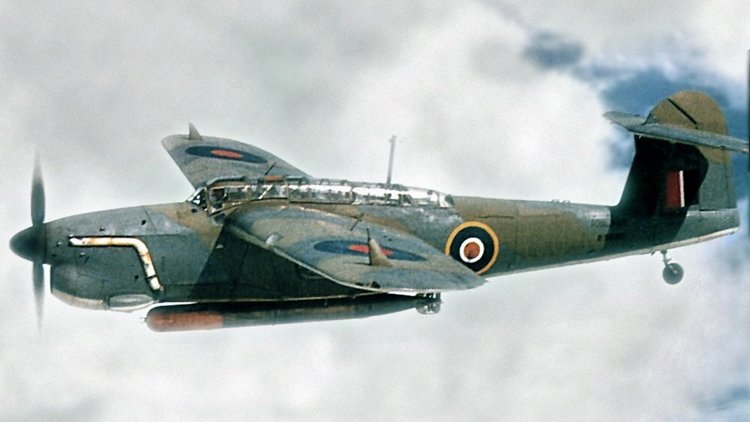 The Fairey Barracuda was a British carrier-borne torpedo and dive bomber designed by Fairey Aviation. It was the first aircraft of this type operated by the Royal Navy's Fleet Air Arm (FAA) to be fabricated entirely from metal. The Barracuda was developed as a replacement for the Fairey Albacore biplanes. Development was protracted due to the original powerplant intended for the type, the Rolls-Royce Exe, being cancelled. It was replaced by the less powerful Rolls-Royce Merlin engine. On 7 December 1940, the first Fairey prototype conducted its maiden flight. Early testing revealed it to be somewhat underpowered. However, the definitive Barracuda Mk II had a more powerful model of the Merlin engine, while later versions were powered by the larger and even more powerful Rolls-Royce Griffon engine. The type was ordered in bulk to equip the FAA. In addition to Fairey's own production line, Barracudas were also built by Blackburn Aircraft, Boulton Paul, and Westland Aircraft. The type participated in numerous carrier operations during the conflict, being deployed in the Atlantic Ocean, Mediterranean Sea, and the Pacific Ocean against the Germans, Italians, and Japanese respectively during the latter half of the war. One of the Barracuda's most noteworthy engagements was a large-scale attack upon the German battleship Tirpitz on 3 April 1944. In addition to the FAA, the Barracuda was also used by the Royal Air Force, the Royal Canadian Navy, the Dutch Naval Aviation Service and the French Air Force. After its withdrawal from service during the 1950s, no intact examples of the Barracuda were preserved despite its once-large numbers, although the Fleet Air Arm Museum has ambitions to assemble a full reproduction. a total of 2602 Barracudas were built. For details of development and operational history, click here. Variants Barracuda Two prototypes (serial numbers P1767 and P1770) based on the Fairey Type 100 design. Mk I First production version, Rolls-Royce Merlin 30 engine with 1,260 hp (940 kW), 30 built Mk II Upgraded Merlin 32 engine with 1,640 hp (1,225 kW), four-bladed propeller, ASV II radar, 1,688 built Mk III Anti-submarine warfare version of Mk II with ASV III radar in a blister under rear fuselage, 852 built Mk IV Mk II (number P9976) fitted with a Rolls-Royce Griffon engine with 1,850 hp (1,380 kW), first flight 11 November 1944, abandoned in favour of Fairey Spearfish. Mk V Griffon 37 engine with 2,020 hp (1,510 kW), payload increased to 2,000 lb (910 kg), ASH radar under the left wing, revised tailfin, 37 built.2 points
 -
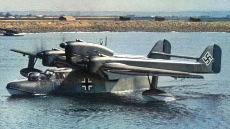 The Blohm & Voss BV 138 Seedrache (Sea Dragon), but nicknamed Der Fliegende Holzschuh ("flying clog", from the side-view shape of its fuselage, as well as a play on the title of the Wagner opera 'Der fliegende Holländer' or 'The Flying Dutchman') was a World War II German trimotor flying boat that served as the Luftwaffe's main seaborne long-range maritime patrol and naval reconnaissance aircraft. A total of 297 BV 138s were built between 1938 and 1943. Originally developed under the company name of Hamburger Flugzeugbau, the type was initially designated the Ha 138. Its appearance was unique in its combination of unusual design features with its twin boom tail unit, short fuselage and trimotor engine configuration. The short hull, with its hydrodynamic step beneath and flat sides, earned it the nickname, "Fliegender Holzschuh" (the flying clog). The booms of the twin tail unit, much like the smaller Focke-Wulf Fw 189 twin-engined reconnaissance monoplane, extended horizontally from the rear of the outer engine nacelles. For hydrodynamic reasons, the hull featured a distinct "turn-down", or "beak" at the stern. The first prototype featured a gull wing, but during the first flight it was discovered that this wing could not generate enough lift, so the concept was abandoned on the second prototype. The airplanes had also a hardpoint for catapult launches from seaplane tenders. Three piston engines were used. The central engine was mounted above the wing, while the wing engines were lower. The pre-production prototypes and the BV 138 A-01 to BV 138 A-06, were powered by various makes of engines ranging from 485 to 746 kW (650–1,000 hp). The first standardized version, BV 138 B-1, was powered by three 880 PS (868 hp, 647 kW) Junkers Jumo 205D two-stroke, opposed-piston aircraft diesel engines. The engine cowlings also had an atypical appearance, due to the unique nature of the vertical orientation of the six-cylinder opposed-piston Jumo 205 diesel engines, and resembled the cowlings of 4 or 6-cylinder inverted inline engines found on smaller civil and utility aircraft from the Jumo 205's propshaft placement, emerging forward at the uppermost front end of the powerplant. The choice for diesel engines made it possible to refuel at sea from U-boats, who also use diesel engines. When refuelling at sea, the airplane had to be fitted with a fuel filter as diesel fuel from ships contains some condensation. Originally developed under the company name of Hamburger Flugzeugbau, the type was initially designated the Ha 138. Its appearance was unique in its combination of unusual design features with its twin boom tail unit, short fuselage and trimotor engine configuration. The short hull, with its hydrodynamic step beneath and flat sides, earned it the nickname, "Fliegender Holzschuh" (the flying clog). The booms of the twin tail unit, much like the smaller Focke-Wulf Fw 189 twin-engined reconnaissance monoplane, extended horizontally from the rear of the outer engine nacelles. For hydrodynamic reasons, the hull featured a distinct "turn-down", or "beak" at the stern. The first prototype featured a gull wing, but during the first flight it was discovered that this wing could not generate enough lift, so the concept was abandoned on the second prototype. The airplanes had also a hardpoint for catapult launches from seaplane tenders. BV 138 being prepared for catapult launch on the aircraft tender Friesenland. Three piston engines were used. The central engine was mounted above the wing, while the wing engines were lower. The pre-production prototypes and the BV 138 A-01 to BV 138 A-06, were powered by various makes of engines ranging from 485 to 746 kW (650–1,000 hp). The first standardized version, BV 138 B-1, was powered by three 880 PS (868 hp, 647 kW) Junkers Jumo 205D two-stroke, opposed-piston aircraft diesel engines. The engine cowlings also had an atypical appearance, due to the unique nature of the vertical orientation of the six-cylinder opposed-piston Jumo 205 diesel engines, and resembled the cowlings of 4 or 6-cylinder inverted inline engines found on smaller civil and utility aircraft from the Jumo 205's propshaft placement, emerging forward at the uppermost front end of the powerplant. The choice for diesel engines made it possible to refuel at sea from U-boats, who also use diesel engines. When refuelling at sea, the airplane had to be fitted with a fuel filter as diesel fuel from ships contains some condensation. There were three gun positions on the aircraft: there was one on the bow with an enclosed, powered gun turret with a single MG 151/20 autocannon. On the stern the fields of fire were obstructed by the tail with the horizontal stabilizer, so there was one gun position lower on the fuselage and a second one higher just behind the central top engine. The gun position behind the central engine, which could see over the horizontal stabilizer, was a fully open Scarff ring-like emplacement which could mount a 7.92 mm MG 15 machine gun, but most aircraft mounted a 13 mm MG 131 heavy machine gun. The lower gun position at the rear fuselage sighted below the horizontal stabilizer. It too was left open and equipped with a machine gun on early aircraft, however later most aircraft mounted an enclosed powered turret similar to the one on the bow. For operational history and variants, click here.2 points
 -
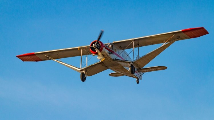 The Bellanca Aircruiser and Airbus were high-wing, single-engine aircraft built by Bellanca Aircraft Corporation of New Castle, Delaware. The aircraft was built as a "workhorse" intended for use as a passenger or cargo aircraft. It was available with wheels, floats or skis. The aircraft was powered by either a Wright Cyclone or Pratt and Whitney Hornet engine. The Airbus and Aircruiser served as both commercial and military transports. The first Bellanca Airbus was built in 1930 as the P-100. An efficient design, it was capable of carrying 12 to 14 passengers depending on the cabin interior configuration, with later versions carrying up to 15. In 1931, test pilot George Haldeman flew the P-100 a distance of 4,400 miles in a time aloft of 35 hours. Although efficient, with a cost per mile figure of eight cents per mile calculated for that flight, the first Airbus did not sell due to its water-cooled engine. The next model, the P-200 Airbus, was powered by a larger, more reliable air-cooled engine. One version (P-200-A) came with floats and operated as a ferry service in New York City, flying between Wall Street and the East River. Other versions included a P-200 Deluxe model, with custom interiors and seating for nine. The P-300 was designed to carry 15 passengers. The final model, the "Aircruiser," was the most efficient aircraft of its day, and would rank high amongst all aircraft designs. With a Wright Cyclone air-cooled supercharged radial engine rated at 715 hp, the Aircruiser could carry a useful load greater than its empty weight. In the mid-1930s, the Aircruiser could carry 4,000 lb payloads at a speed of between 145 and 155 mph, a performance that multi-engine Fokkers and Ford Trimotors could not come close to matching. In 1934, United States federal regulations prohibited single-engine transports on United States airlines, virtually eliminating future markets for the Aircruiser. Where the workhorse capabilities of the Aircruiser stood out was in Canada. Several of "The Flying Ws", as it was commonly dubbed in Canada, were used in northern mining operations, ferrying ore, supplies and the occasional passenger, into the 1970s. Variants Airbus Bellanca P Commercial version of Bellanca K, powered by a 500 hp (370 kW) Pratt & Whitney R-1860 Hornet.[2] P-100 Airbus 14-passenger monoplane powered by a 600 hp (450 kW) Curtiss Conqueror engine, one built, later converted into a P-200. P-200 Airbus 12-passenger monoplane, nine built and one converted from P-100. P-300 Airbus 15-seater monoplane powered by a Wright R-1820 Cyclone engine. Y1C-27 United States Army Air Corps designation for four P-200 Airbuses powered by 550 hp (410 kW) Pratt & Whitney R-1860 Hornet B engine. All later converted to C-27C. C-27A Airbus Production version of the Y1C-27 powered by a 650 hp (480 kW) Pratt & Whitney R-1860 Hornet B engine, ten built. One converted to a C-27B the rest converted to C-27Cs. C-27B Airbus One C-27A re-engined with a 675 hp (503 kW) Wright R-1820-17 Cyclone engine. C-27C Airbus Four Y1C-27s and nine of the C-27A re-engined with a 750 hp (560 kW) Wright R-1820-25 Cyclone engine. Aircruiser Aircruiser 66-67 Improved structure modified from a P-200 with a 675 hp (503 kW) Wright SR-1820 Cyclone engine Aircruiser 66-70 (Specifications below) An Aircruiser with a 710 hp (530 kW) Wright SGR-1820 Cyclone engine, five built - exported to Canada. Aircruiser 66-75 An Aircruiser with a 730 hp (540 kW) Wright Cyclone engine, three built. Aircruiser 66-76 A cargo-version of the Aircruiser with a 760 hp (570 kW) Wright Cyclone. Aircruiser 66-80 An Aircruiser with an 850 hp (630 kW) Wright Cyclone engine.2 points
 -
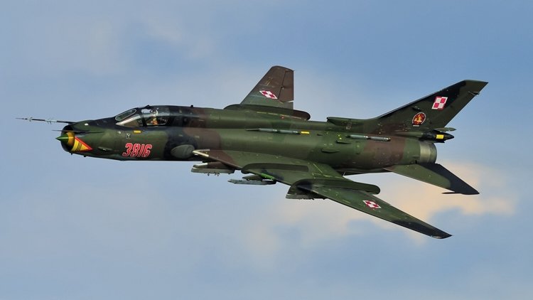 The Sukhoi Su-17 (izdeliye S-32) is a variable-sweep wing fighter-bomber developed for the Soviet military. Its NATO reporting name is "Fitter". Developed from the Sukhoi Su-7, the Su-17 was the first variable-sweep wing aircraft to enter Soviet service and was featured updated avionics. The aircraft also has variants which were designed to be exported to non-Soviet states such as the Sukhoi Su-22 and the less popular Su-20. It was produced from 1967-1990. The Su-17/20/22 series had a long career and has been operated by many air forces, including those of the Russian Federation, former Soviet republics, former Warsaw Pact, countries in the Arab world, Angola, and Peru. The Russian Federation retired its fleet in 1998. Although the Su-17 was capable of carrying nuclear weapons, it was used in roles ranging from close-air support to ground attack. Shortly after the Su-7 fighter-bomber was put into service, the Sukhoi Design Bureau was ordered to develop a modernization program. The program would be aimed primarily at updating on-board avionics and takeoff/landing characteristics. The concept of variable-geometry wings - something gaining wider attention at that time - was adopted. The program was to be led by Sukhoi's head designer, Nikolay Zyrin. In 1963 the Sukhoi OKB with input from TsAGI created a variable-sweep wing technology demonstrator. The S-22I (also known as the Su-7IG, NATO designation "Fitter-B"), converted from a production Su-7BM, had fixed inner portions of the wing with movable outer segments that could be swept to 28°, 45°, or 62°. The S-22I first took off (with Vladimir Ilyushin at the controls) on 2 August 1966. It was later demonstrated at the air parade in Domodedovo in July 1967. Flight testing revealed that the configuration improved both take-off/landing characteristics, range and endurance. Handling was generally better than the fixed wing Su-7, with the exception that buffeting at high angles of attack to warn of imminent stall no longer occurred. For further details of the deveopment, operational history and variants of the series, click here. The photos on this page feature the Su-22 of the Polish Air Force, and the specifications below are for the Su-17M4.2 points
 -
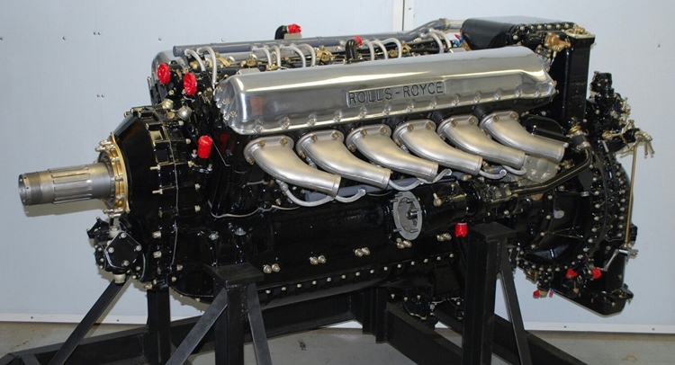 The Rolls Royce Merlin was the beating heart of any number of WWII military aircraft - and would you believe that it powered the Cromwell Cruiser tank? This link is to a lecture given by one of the developers of teh Merlin engine to de Haviland technical people in late 1945. I post it here in order to preserve it. http://www.wwiiaircraftperformance.org/merlin-lovesey.pdf The Rolls Royce Merlin fitted in a Spitfire Just some of the aircraft powered by Rolls Royce Merlin engines. Avro Lancaster Hawker Hurricane Supermarine Spitfire CAC CA-18 Mustang2 points
 -
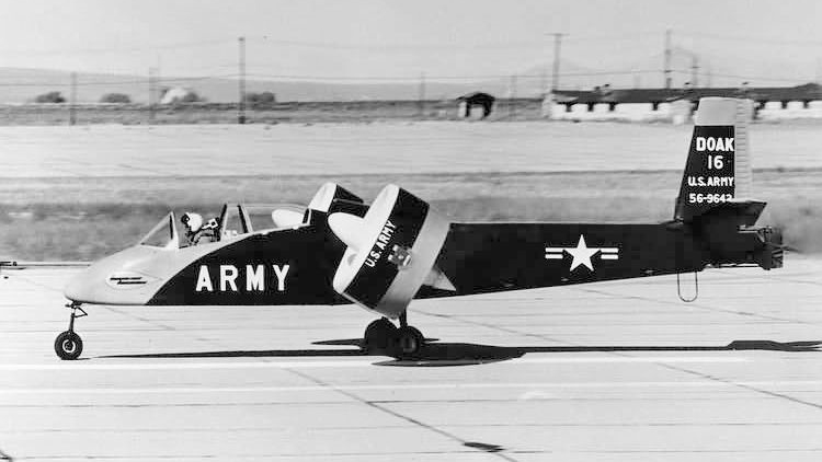 The Doak VZ-4 (or Doak Model 16) was an American prototype Vertical Takeoff and Landing (VTOL) aircraft built in the 1950s for service in the United States Army. Only a single prototype was built, and the U.S. Army withdrew it from active trials in 1963. Edmund R. Doak, Jr., a self-taught engineer and vice president of Douglas Aircraft Company, founded Doak Aircraft Company in Torrance, California, in 1940. The company grew to 4,000 employees during World War II, with subcontracts from every major American aircraft manufacturer. These included molded plywood fuselages for trainers such as the AT-6 and Vultee BT-13, and doors, hatches and gun turrets for a multitude of aircraft. Doak proposed a VTOL aircraft to the U.S. Army's Army Transportation and Research and Engineering Command at Fort Eustis in Newport News, Virginia, in 1950. He touted the aircraft as able to take off and land in a small area, hover and loiter over a target area, and fly backwards like a helicopter without the noise and vibration of a helicopter, while also having the horizontal cruising ability, high speed, wing-mounted weapons, and mission flexibility of a conventional fixed-wing fighter aircraft. Knowing that a Soviet attack on airbases would interdict takeoffs and landings by conventional aircraft, the Army found Doak's proposal attractive, and on 10 April 1956, it awarded Doak a contract to produce a single prototype for use as a research aircraft. The aircraft, designated the Doak Model 16 by the Doak company and assigned the serial number 56-9642, was originally powered by an 840 shp (630 kW) Lycoming YT53 turboprop engine mounted in the fuselage, later replaced by a 1,000 shp (750 kW) Lycoming T53-L-1 turbine. The engine drove two wingtip-mounted fiberglass tilting ducted fan propellers through a "T" box on the engine that transmitted power to the propellers via a 4-inch (102-mm) aluminum tubular shaft and two smaller shafts. Each propeller was 48-inch (1.22-meter) in diameter and the duct outer diameter was 60-inches (1.52-meter)). The fans were positioned vertically for takeoff and landing – with a rotation speed of 4,800 rpm required for liftoff – and rotated to a horizontal orientation for horizontal flight, the first time this VTOL propulsion concept was tested successfully. The aircraft had metal wings and a metal tail. To save weight, the aircraft originally was constructed of uncovered welded steel tubing, but after it was found that the open frame interfered with forward-speed tests, molded fiberglass was installed over its nose section and thin aluminum sheeting over its aft fuselage. It accommodated a two-person crew, with a pilot and observer seated in tandem in the cockpit. The pilot used a standard stick and rudder to control the aircraft. Its landing gear were taken from a Cessna 182 Skylane, its seats from a North American P-51 Mustang, and its duct actuators from a Lockheed T-33 Shooting Star. Flight testing began at Torrance Municipal Airport, and Doak completed several tests by 1958. The Model 16 hovered for the first time on 25 February 1958, and the first transition from vertical to horizontal flight (and back again) took place on 5 May 1958. Although the prototype generally was successful, its short takeoff and landing performance was less than hoped for and it displayed a tendency to nose up while making the transition from vertical to horizontal flight. Doak's engineers believed that they could solve the prototype's problems, and after taxiing testing, 32 hours of flight testing in a test stand, and 18 hours of tethered hovering, the aircraft was transferred to Edwards Air Force Base, California, in October 1958. It underwent another 50 hours of testing, in which it proved capable with the turbine engine of achieving a maximum speed of 230 mph (370 km.hr), a cruise speed of 175 mph (282 km/hr), a range of 250 miles (403 km), an endurance of one hours, and a service ceiling of 12,000 feet (3,658 meters).2 points
 -
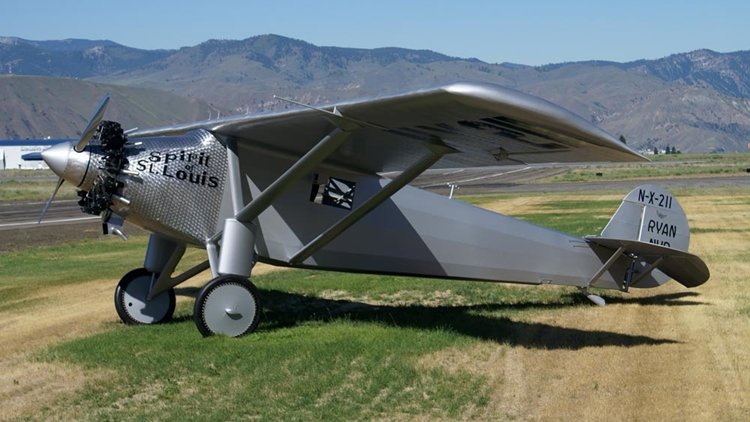 The Spirit of St. Louis (formally the Ryan NYP, registration: N-X-211) is the custom-built, single-engine, single-seat, high-wing monoplane that was flown by Charles Lindbergh on May 20–21, 1927, on the first solo nonstop transatlantic flight from Long Island, New York, to Paris, France, for which Lindbergh won the $25,000 Orteig Prize. Lindbergh took off in the Spirit from Roosevelt Airfield, Garden City, New York, and landed 33 hours, 30 minutes later at Aéroport Le Bourget in Paris, France, a distance of approximately 3,600 miles (5,800 km). One of the best-known aircraft in the world, the Spirit was built by Ryan Airlines in San Diego, California, owned and operated at the time by Benjamin Franklin Mahoney, who had purchased it from its founder, T. Claude Ryan, in 1926. The Spirit is on permanent display in the main entryway's Milestones of Flight gallery at the Smithsonian Institution's National Air and Space Museum in Washington, D.C. Officially known as the "Ryan NYP" (for New York to Paris), the single-engine monoplane was designed by Donald A. Hall of Ryan Airlines and named the "Spirit of St. Louis" in honor of Lindbergh's supporters from the St. Louis Raquette Club in his then hometown of St. Louis, Missouri. To save design time, the NYP was loosely based on the company's 1926 Ryan M-2 mailplane, the main difference being the NYP's 4,000-mile (6,400 km) range. As a nonstandard design, the government assigned it the registration number N-X-211 (for "experimental"). Hall documented his design in "Engineering Data on the Spirit of St. Louis", which he prepared for the National Advisory Committee for Aeronautics (NACA) and is included as an appendix to Lindbergh's 1953 Pulitzer Prize winning book The Spirit of St. Louis. B.F. "Frank" Mahoney and Claude Ryan had co-founded the company as an airline in 1925 and Ryan remained with the company after Mahoney bought out his interest in 1926, although there is some dispute as to how involved Ryan may have been in its management after selling his share. It is known, however, that Hawley Bowlus was the factory manager who oversaw construction of the Ryan NYP, and that Mahoney was the sole owner at the time of Donald A. Hall's hiring. The Spirit was designed and built in San Diego to compete for the $25,000 Orteig Prize for the first nonstop flight between New York and Paris. Hall and Ryan Airlines staff worked closely with Lindbergh to design and build the Spirit in just 60 days. Although what was actually paid to Ryan Airlines for the project is not clear, Mahoney agreed to build the plane for $6,000 and said that there would be no profit; he offered an engine, instruments, etc. at cost. After first approaching several major aircraft manufacturers without success, in early February 1927 Lindbergh, who as a U.S. Air Mail pilot was familiar with the good record of the M-1 with Pacific Air Transport, wired, "Can you construct Whirlwind engine plane capable flying nonstop between New York and Paris ...?" Mahoney was away from the factory, but Ryan answered, "Can build plane similar M-1 but larger wings... delivery about three months." Lindbergh wired back that due to competition, delivery in less than three months was essential. Many years later, John Vanderlinde, chief mechanic of Ryan Airlines, recalled, "But nothing fazed B.F. Mahoney, the young sportsman who had just bought Ryan." Mahoney telegraphed Lindbergh back the same day: "Can complete in two months." Lindbergh was convinced: "I believe in Hall's ability; I like Mahoney's enthusiasm. I have confidence in the character of the workmen I've met."[citation needed] He then went to the airfield to familiarize himself with a Ryan aircraft, either an M-1 or an M-2, then telegraphed his St. Louis backers and recommended the deal, which was quickly approved. Mahoney lived up to his commitment. Working exclusively on the aircraft and closely with Lindbergh, the staff completed the Spirit of St. Louis 60 days after Lindbergh arrived in San Diego. Powered by a Wright Whirlwind J-5C 223-hp radial engine, it had a 14 m (46-foot) wingspan, 3 m (10 ft) longer than the M-1, to accommodate the heavy load of 1,610 L (425 gal) of fuel. In his 1927 book We, Lindbergh acknowledged the builders' achievement with a photograph captioned "The Men Who Made the Plane", identifying: "B. Franklin Mahoney, president, Ryan Airlines", Bowlus, Hall and Edwards standing with the aviator in front of the completed aircraft. Lindbergh believed that multiple engines resulted in a greater risk of failure while a single-engine design would give him greater range. To increase fuel efficiency, the Spirit of St. Louis was also one of the most advanced and aerodynamically streamlined designs of its era. Lindbergh believed that a flight made in a single-seat monoplane designed around the dependable Wright J-5 Whirlwind radial engine provided the best chance of success. The Ryan NYP had a total fuel capacity of 450 U.S. gallons (1,700 L; 370 imp gal) or 2,710 pounds (1,230 kg) of gasoline, which was necessary in order to have the range to make the anticipated flight non-stop. The fuel was stored in five fuel tanks, a forward tank – 88 U.S. gal (330 L; 73 imp gal), the main – 209 U.S. gal (790 L; 174 imp gal), and three wing tanks – total of 153 U.S. gal (580 L; 127 imp gal).[5] Lindbergh modified the design of the plane's "trombone struts" attached to the landing gear to provide a wider wheelbase in order to accommodate the weight of the fuel. At Lindbergh's request, the large main and forward fuel tanks were placed in the forward section of the fuselage, in front of the pilot, with the oil tank acting as a firewall. This arrangement improved the center of gravity and reduced the risk of the pilot being crushed to death between the main tank and the engine in the event of a crash. This design decision meant that there could be no front windshield, and that forward visibility would be limited to the side windows. This did not concern Lindbergh as he was accustomed to flying in the rear cockpit of mail planes with mail bags in the front. When he wanted to see forward, he would slightly yaw the aircraft and look out the side. To provide some forward vision as a precaution against hitting ship masts, trees, or structures while flying at low altitude, a Ryan employee who had served in the submarine service installed a periscope which Lindbergh helped design. It is unclear whether the periscope was used during the flight. The instrument panel housed fuel pressure, oil pressure and temperature gauges, a clock, altimeter, tachometer, airspeed indicator, bank and turn indicator, and a liquid magnetic compass. The main compass was mounted behind Lindbergh in the cockpit, and he read it using the mirror from a women's makeup case which was mounted to the ceiling using chewing gum. Lindbergh also installed a newly developed Earth Inductor Compass made by the Pioneer Instrument Company which allowed him to more accurately navigate while taking account of the magnetic declination of the earth. Lindbergh's ultimate arrival in Ireland deviated from his flight plan by just a few miles. Lindbergh sat in a cramped cockpit which was 94 cm wide, 81 cm long and 130 cm high (36 in × 32 in × 51 in). The cockpit was so small, Lindbergh could not stretch his legs. The Spirit of St. Louis was powered by a 223 hp (166 kW), air-cooled, nine-cylinder Wright J-5C Whirlwind radial engine. The engine was rated for a maximum operating time of 9,000 hours (more than one year if operated continuously) and had a special mechanism that could keep it clean for the entire New York-to-Paris flight. It was also, for its day, very fuel-efficient, enabling longer flights carrying less fuel weight for given distances. Another key feature of the Whirlwind radial engine was that it was rated to self-lubricate the engine's valves for 40 hours continuously. Lubricating, or "greasing," the moving external engine parts was a necessity most aeronautical engines of the day required, to be done manually by the pilot or ground crew prior to every flight and would have been otherwise required somehow to be done during the long flight. The engine was built at Wright Aeronautical in Paterson, New Jersey by a 24-year-old engine builder, Tom Rutledge, who was disappointed that he was assigned to the unknown aviator, Lindbergh. Four days after the flight, he received a letter of congratulations from the Wright management. For more information, click here.2 points
 -
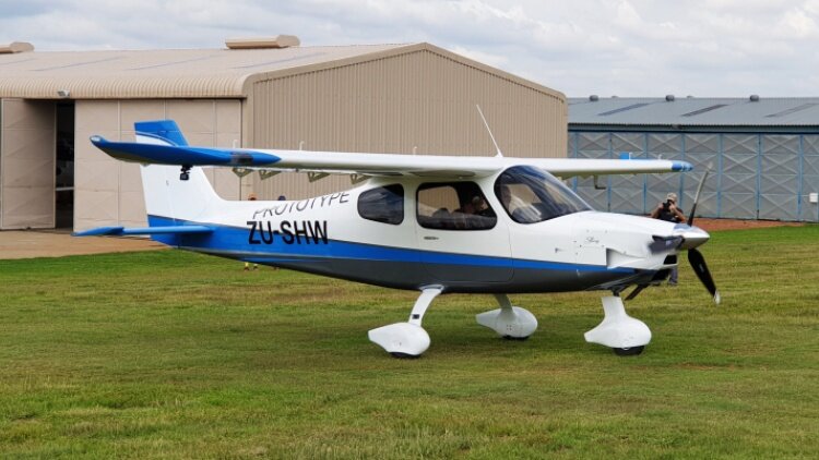 The most anticipated version of the phenomenally successful Sling series is the Sling High Wing. The High Wing – or just Sling HW – was first proposed as a high wing version of the Sling 2 at the same time as founder Mike Blyth started work on the original Sling 2 back in 2005. The final product has come a long way from the early Sling 2s. The Sling TSi is unique in that it is the only aircraft that comes in almost identical low wing and high wing versions. For this reason the comparison with the low wing Sling TSI is particularly interesting. The rationale for developing both a low wing and a high wing are many. Mike Blyth provides the following reasons: “The engine–airframe combination of the Sling TSi is so perfect that to fail to exploit it in a high wing model would feel like a crime. Also, there’s a real gap in the market as there is no other aircraft in that space. And you can see really well out of a high wing when flying straight, and it can be a great camera and/ or surveillance platform.” The Sling HW made its first flight as promised before the end of 2020. That development and construction had continued through the Covid lockdown is testimony to the dedication and commitment the Sling team brought to the project. A readily noticeable difference between the Low Wing and High is that the high has a vertical fin and rudder a full 20 cm longer than the Low Wing. Given the High Wing ‘nosedraggers’ high stance, this may make getting the tail under a low hangar door opening something to watch. The Sling HW and TSi are immediately distinguishable by the large NACA duct on the right side of the cowl which feeds air into the engine’s high-volume intercooler. Sling Aircraft has done a great job integrating this duct into the Sling’s distinctive shark nose cowling. For the full write-up from which these notes were extracted click here.2 points
 -
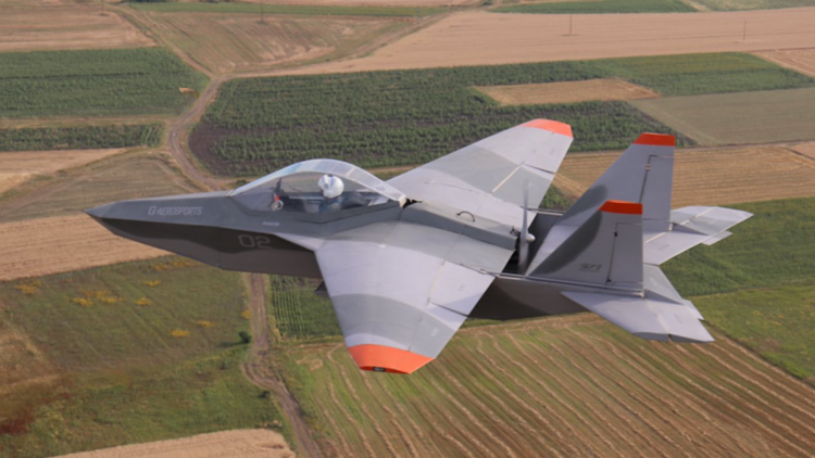 Archon SF-1 is an evolutionary unique aircraft, that utilizes the look of a modern fighter aircraft but lies into the Ultalight(EU)/LSA(USA) category. The idea behind the design is an affordable recreational aircraft that offers the impression and the feeling of a fighter aircraft. It was designed and built in Greece, by George Iliopoulos. The maiden flight was made in July, 2009. Since then, it’s been being test flown in regular basis and have received minor changes to improve the overall flight qualities. The standard engine mount is for the Rotax 503, 532, 582 engines.Alluminum alloy construction, light-weight and durable material, corrosion resistant, UV protected. Easy to work with.Basic skills and tools required to assemble in a small workshop.2 points
 -
 The Junkers G.38 was a large German four-engined transport aircraft which first flew in 1929. Two examples were constructed in Germany. Both aircraft flew as a commercial transport within Europe in the years leading up to World War II. During the 1930s, the design was licensed to Mitsubishi, which constructed and flew a total of six aircraft, in a military bomber/transport configuration, designated Ki-20. The G.38 carried a crew of seven. Onboard mechanics were able to service the engines in flight due to the G.38's blended wing design, which provided access to all four power plants. During the 1920s, Hugo Junkers made several attempts to produce a large scale commercial transport. His initial attempt, the four-engined JG1, was developed during 1921-1922; but Junkers was forced to destroy the incomplete airplane based on post-WWI Allied demands citing the Treaty of Versailles. Later in the decade, in 1925, he published design specifications for a proposed eighty passenger trans-Atlantic aircraft - the J.1000 project. Then again, towards the end of the decade, the G.40 project was started by the Junkers design team as a trans-Atlantic mail plane. From the G.40 design, which was a seaplane configuration, Junkers also developed a landplane design, designated the G.38. Despite interest from the German armed forces in the G.40 variant, Junkers pushed forward with the landplane design which, having received financing from the Reich Air Ministry (Reichsluftfahrtministerium), was taken forward to the construction stage. The first Junkers prototype—3301 and marked as D-2000—first flew on 6 November 1929 with four diesel engines: two Junkers L55 V-12 engines and two 294 kW L8 inline-6 engines, with a total power rating of 1470 kW (1971 hp). The Reich Air Ministry purchased the D-2000 for demonstration flights, and took delivery on 27 March 1930. In flight tests, the G.38 set four world records including speed, distance and duration for airplanes lifting a 5000 kg payload. On 2 May 1930 Luft Hansa put the D-2000 into commercial service for both scheduled and chartered flights. Structurally the G.38 conformed to standard Junkers' practice, with a multi-tubular spar cantilever wing covered (like the rest of the aircraft) in stressed, corrugated duraluminium. The biplane tail, found in other large aircraft of the time, was intended to reduce rudder forces; initially there were three rudders with only a central fixed fin. The undercarriage was fixed, with double tandem main wheels that were initially enclosed in very large spats. The wing had the usual Junkers "double wing" form, the name referring to the full span movable flaps which served also as ailerons in the outer part. On 2 February 1931 the Leipzig-based Junkers' yard re-engined the D-2000 with two Junkers L8 and two L88 engines, giving a total power rating of 1764 kW (2366 hp) and increasing passenger capacity from 13 to 19. During its early life the G.38 was the largest landplane in the world. Passenger accommodation was sumptuous by today's standards and was meant to rival that found on the competing Zeppelin service offered by DELAG. The plane was unique in that passengers were seated in the wings, which were 1.7 m (5 ft 7 in) thick at the root. There were also two seats in the extreme nose. The leading edge of each wing was fitted with sloping windscreens giving these passengers the forward-facing view usually available only to pilots. There were three 11-seat cabins, plus smoking cabins and washrooms. In design terms the G-38 followed the Blended Wing Body design pioneered by Louis de Monge, later followed by Vincent Burnelli in his UB14 and later CBY-3 designs, and even later considered by both NASA and Boeing as an alternative to traditional tube and wing aircraft configurations. For operational history, click here.2 points
 -
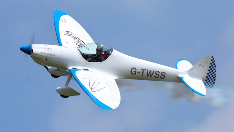 The Silence Twister is a German ultralight designed by Silence Aircraft for amateur construction, either from plans or kits. The prototype first flew on 30 September 2000. The Twister is a single-seat low-wing monoplane with elliptical wings and tailplane. It has a retractable conventional landing gear with a fixed tailwheel. The design drew inspiration from the Supermarine Spitfire, and the shapes of the Twister's wings, fin and tailplane all recall the famous World War II fighter. Designed to take engines up to 94 hp (70 kW), the prototype was fitted with a 53.6 hp (40 kW) single-rotor MidWest Wankel engine. This compact rotary motor allowed a sleek engine cowling, but the engine was rejected and production aircraft use 85 hp (63 kW) Jabiru 2200 or 95 hp (71 kW) ULPower UL260i engines. An electric aircraft version was under development in 2010. The Twister prototype was fitted with Silence Aircraft's own automatic variable-pitch propeller called the "VProp". The LAA have yet to allow the VProp to be fitted on UK aircraft, so UK Twisters have fixed-blade propellers instead. Twenty-one examples had been completed and flown by December 2011. Variants SA155 Initial prototype powered by a 34 kW (45 hp) MidWest AE50 Wankel rotary engine. The second prototype was powered by a 34 kW (45 hp) Diamond AE50 engine.[2] SA180 powered by a 60 kW (80 hp) Jabiru 2200 engine.[2] Akron A version developed for the US market under Experimental aircraft certification rules.2 points
 -
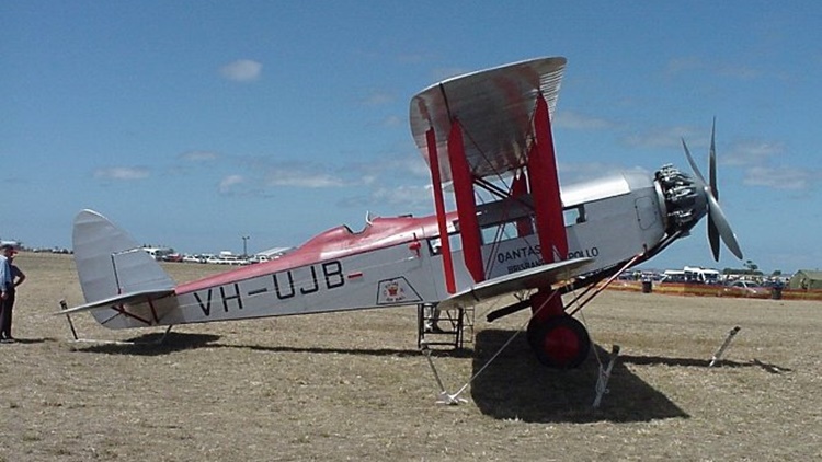 Following the success of the de Havilland DH.50J in Australia, the company was asked to design a larger replacement using a Bristol Jupiter engine. The cabin had room for six to eight passengers with the pilot in an open cockpit behind the wings. The aircraft took only 10 weeks to design and the prototype first flew in December 1927. Following test flights in England, the aircraft was sent to de Havilland Australia in Melbourne. After reassembly, the prototype first flew on 2 March 1928 and was used on scheduled services between Adelaide and Broken Hill by MacRobertson Miller Aviation. The prototype was originally called Canberra which was used as a type name until it was changed to Giant Moth. A total of 10 aircraft were built, including one in Canada built from components with the rest coming from the Stag Lane production line. Three aircraft for Canada (G-CAPG), (G-CARD) and (G-CAJT) were fitted with Short Brothers floats at Rochester before one was delivered to Canadian Vickers. Three aircraft were used in Australia on air mail services by Australian Aerial Services Ltd and QANTAS. The two QANTAS Giant Moths, Apollo (G-AUJB) and Diana (G-AUJC), were acquired in April and May 1929 respectively. They were the first QANTAS aircraft equipped with toilets. The airline took them out of service in 1935 because the Bristol Jupiter XI engines were unreliable. Apollo was sold that year and crashed near Mubo, New Guinea, on 9 May 1938. Another aircraft, Geraldine (G-AAAN), was bought by the Daily Mail to carry a photographer and his motorcycle around the United Kingdom. For more information, click here.2 points
 -
 Powered by four turboprop engines each driving a pair of contra-rotating propellers, the design was the first wide-body transport aircraft and remains the world's largest turboprop-powered aircraft to date. The An-22 first appeared publicly outside the Soviet Union at the 1965 Paris Air Show. Thereafter, the model saw extensive use in major military and humanitarian airlifts for the Soviet Union, and is still in service with the Russian Air Force. In the late 1950s, the Soviet Union required a large military transport aircraft to supplement the Antonov An-8 and An-12s then entering service. Originally known as the An-20, the model is a conventional multi-engined high-wing design. In the early 1960s, the Antonov bureau produced a wooden mock up at its Kyiv, Ukraine, workshops of what was designated the Model 100. The prototype, now designated the An-22, was rolled out on 18 August 1964 and first flew on 27 February 1965. The prototype was given the name Antaeus (sometimes misspelled Antheus) and, after four-months of test flying, was displayed at the 1965 Paris Air Show. All aircraft were built at the Tashkent State Aircraft Factory and the first military delivery was made to the Air Transport Wing at Ivanovo Airbase in 1969. The aircraft was designed as a strategic airlifter, designed specifically to expand the Soviet Airborne Troops' capability to land with their then-new BMD-1 armoured vehicles. The An-22 cargo hold can accommodate four BMD-1s compared to only one in the An-12. It has the capability to takeoff from austere, unpaved, and short airstrips, allowing airborne troops to perform air-landing operations. This is achieved by four pairs of contra-rotating propellers, similar to those on the Tupolev Tu-114. The propellers and exhaust from the engines produce a slipstream over the wings and large double-slotted flaps. The landing gear is ruggedized for rough airstrips. In early versions tire pressures could be adjusted in flight for optimum landing performance. That feature was removed in later models. A total of 69 units were built. For more information on the development, operational history and variants, click here.2 points
 -
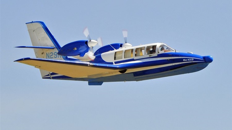 Intended for autonomous operation in the unmarked areas of Russia's far north and Siberia, the Be-103 was designed for short-haul routes in regions that have rivers, lakes and streams, but are otherwise inaccessible. The Be-103 is a mid-wing monoplane, making use of the modified wing roots as water-displacing sponsons. It features an all-moving slab tail and retractable tricycle landing gear for land operations. Its hallmark and most distinguishing design feature is the water-displacing wing, an unusual feature for a seaplane, with three aquaplaning implements (planing step, port and starboard wing trailing edges) which substantially enhance the aircraft's on-the-water stability and seaworthiness. The Be-103 features include an advanced, blended wing, swept at 22°, with 11-foot (3.4 m)-long fixed leading edge slats, trailing-link main landing gear, and three-bladed MT-12 reverse pitch propellers. Fuel is stored in the wet wings. The aircraft is built from aluminum-lithium alloy with titanium used in high-stress areas. A 30-parameter, five-hour flight data recorder, engine fire-detection systems and an ice detector are also standard, as are hydraulic brakes. However, unlike most modern aircraft, the Be-103 is not equipped with wing flaps. When flying solo, ballast must be placed near the right front seat due to center of gravity issues. As of 2010, three aircraft were on the United States civil register. In 2004 China signed a US$20mil contract with KnAAPO for the delivery of 20 aircraft. In 2016 contract was signed between Taganrog-based Beriev Aircraft Company and the Chinese Energy Leader Aircraft Manufacturing to start licensed production of Beriev Be-103 in China. Variants Be-103 Twin-engine light utility amphibian aircraft, seating one pilot and five passengers. SA-20P Eight-seat version powered by single VOKEM M14X radial engine; one prototype.2 points
 -
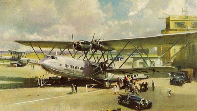 They held the distinction of being the largest airliners in regular use in the world upon the type's introduction in 1931. The H.P.42/45 were designed in response to a specification issued during 1928 by British airline Imperial Airways; the two models share considerable similarities, the H.P.42 being optimised towards greater range at the expense of payload while the H.P.45 had these priorities inverted, allowing the latter to carry more passengers over shorter distances. Imperial Airways approved of Handley Page's proposals and ordered four aircraft of the two variants to serve as the new land-based long-distance flagships of its fleet. On 14 November 1930, the prototype, named Hannibal, conducted its maiden flight. Following their introduction into Imperial Airways, they formed the backbone of the airliner's land-based fleet through most of the 1930s and, along with the company's numerous flying boats, have been considered to be icons of their era. A total of eight aircraft were built, four of each type; all were named, with names beginning with the letter "H". Three of the survivors were pressed into Royal Air Force (RAF) service at the outbreak of the Second World War. By the end of 1940, all of the aircraft had been destroyed as a result of several accidents. In total, four H.P.42 and four H.P.45 aircraft were delivered, but two of the HP45s were later converted into HP42s. The H.P.45 carried more passengers with a reduced range and baggage capacity, and was intended for Imperial Airways' European routes. For details of the development, design, operational history and individual histories of each of the eight aircraft, click here. The specifications below are for the H.P.42 variant.2 points
 -
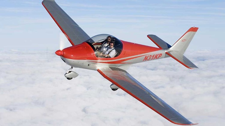 It is a conventional low-wing monoplane featuring all-metal construction and tricycle undercarriage. Jilhavan Aircraft built the Kappa Sova for Kappa 77 from 1997 to 2004 and obtained marketing rights in 2005 when Kappa became insolvent. They became a subsidiary of Skyleader Aircraft in 2008 when the type was redesignated Jihlavan Skyleader. It is an all-metal design apart from a carbon fibre cockpit frame. It has two-spar tapered wings with 6° of dihedral, electrically operated Fowler flaps and upturned Küchemann tips. The fin and rudder are swept. The straight tapered tailplane is set on top of the fuselage, the port elevator carrying a trim tab. The original Sova/Skyleader 150 has staggered side-by-side configuration seating with the starboard seat 200 mm (8 in) aft of the other, but a widened fuselage allows the Skyleader 200 to have true side-by-side seating. The earlier version has a forward-hinged canopy with fixed rear transparencies; the Skyleader 200 has a single-piece canopy. Both these variants normally have an electrically actuated tricycle undercarriage with a steerable nosewheel, though a fixed version is an option and is standard on the later Skyleader 500 and 600 variants. For more details of the development and design, operational history and variants, click here. Specifications below are for the KP-2U Sova variant.2 points
 -
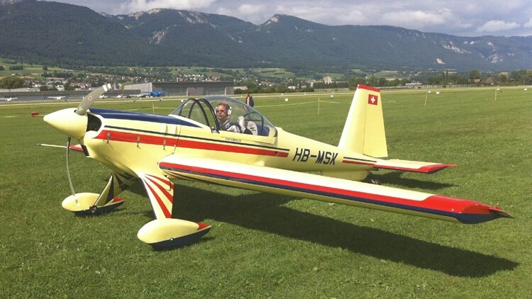 he Hirth Hi 27 Acrostar was designed by Arnold Wagner to win aerobatic competitions, in part by having handling independent of orientation, upright or inverted. A single engine, single seat low-wing monoplane, it was built in West Germany by Wolf Hirth GmbH in the early 1970s, and dominated Championships for a brief period. The Hirth Hi 27 Acrostar is a competition aerobatic aircraft designed by the Swiss aerobatic champion, Arnold Wagner. Wagner and three others, two of them German ex-champions, sponsored the construction. The Wolf Hirth team was led by Prof. Richard Eppler of the Stuttgart Technische Hochschule, starting work in the Summer of 1969. The first flight of what was known as the Acrostar Mk II was on 16 April 1970. The Acrostar is a conventionally arranged low wing single engine aircraft. The wing is straight tapered, the leading edge slightly swept and the trailing edge unswept. The aerofoil section, designed by Eppler, is quite thick with a thickness-to-chord ratio of 20%. It is a symmetric section and mounted at zero incidence. There is also zero dihedral. Full span control surfaces are fitted, flaps inboard and proportionally moving ailerons outboard. The ailerons are balanced not by the usual horn or hinge line extensions but by small surfaces which project beyond the wingtips. Unusually, both ailerons and flaps are coupled to the elevator position; this camber changing control system, together with the highly symmetric wing, produces the same control characteristics for normal and inverted manoeuvres. The basic idea in this arrangement was to keep the centerline of the fuselage horizontal in both normal and inverted horizontal flight. The result, beside this, is good controllability in low speed ballistic flight, around zero G. Another unusual control feature, allowing for independent trimming in pitch and yaw, are the independent trim tabs on the flaps. The plywood covered wing is built around a single glass fibre spar using foam reinforced ribs. Aft of the engine, the fuselage is a wooden semi-monocoque. The single seat cockpit is enclosed with a rearward sliding canopy. The fin and balanced rudder are straight tapered and square tipped, as is the rearward set horizontal tail. The prototype had elevator trim tabs but these were removed in favour of the flap trims noted above. Extra fin area is provided by a long strake on the lower fuselage, extending aft to the tailwheel. The Acrostar is powered by a 220 hp (165 kW) Franklin 6A-350-C1 six cylinder horizontally opposed piston engine. This is mounted in a steel frame which is integral with the fixed cantilever main undercarriage and its optionally streamlined, tapering legs and faired wheels. This arrangement places the main landing gear further forward than usual, providing a drag moment to oppose that of the fin in vertical flight. The tailwheel is steerable. For details of operational history, click here.1 point
 -
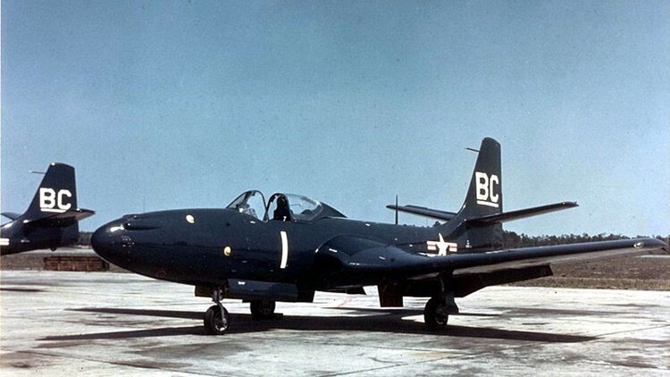 The McDonnell FH Phantom is a twinjet, straight-wing, carrier-based fighter aircraft designed and first flown during late World War II for the United States Navy. As a first-generation jet fighter, the Phantom was the first purely jet-powered aircraft to land on an American aircraft carrier and the first jet deployed by the United States Marine Corps. Although only 62 FH-1s were built it helped prove the viability of carrier-based jet fighters. As McDonnell's first successful fighter, it led to the development of the follow-on F2H Banshee, which was one of the two most important naval jet fighters of the Korean War; combined, the two established McDonnell as an important supplier of navy aircraft. McDonnell chose to bring the name back with the third-generation, Mach 2-capable McDonnell Douglas F-4 Phantom II, the most versatile and widely used Western combat aircraft of the Vietnam War era. The FH Phantom was originally designated the FD Phantom, but this was changed as the aircraft entered production. In early 1943, aviation officials at the United States Navy were impressed with McDonnell's audacious XP-67 Bat project. McDonnell was invited by the navy to cooperate in the development of a shipboard jet fighter, using an engine from the turbojets under development by Westinghouse Electric Corporation. Three prototypes were ordered on 30 August 1943 and the designation XFD-1 was assigned. Under the 1922 United States Navy aircraft designation system, the letter "D" before the dash designated the aircraft's manufacturer. The Douglas Aircraft Company had previously been assigned this letter, but the USN elected to reassign it to McDonnell because Douglas had not provided any fighters for navy service in years. McDonnell engineers evaluated a number of engine combinations, varying from eight 9.5 in (24 cm) diameter engines down to two engines of 19 inches (48 cm) diameter. The final design used the two 19 in (48 cm) engines after it was found to be the lightest and simplest configuration. The engines were buried in the wing root to keep intake and exhaust ducts short, offering greater aerodynamic efficiency than underwing nacelles, and the engines were angled slightly outwards to protect the fuselage from the hot exhaust blast. Placement of the engines in the middle of the airframe, behind the center of gravity, required the cockpit with its bubble-style canopy to be placed ahead of the wing, also granting the pilot excellent visibility in all directions. The long nose allowed designers to use tricycle gear, thereby elevating the engine exhaust path and reducing the risk that the hot blast would damage the aircraft carrier deck. The construction methods and aerodynamic design of the Phantom were fairly conventional for the time; the aircraft had unswept wings, a conventional empennage, and an aluminum monocoque structure with flush riveted aluminum skin. Folding wings were used to reduce the width of the aircraft in storage configuration. Provisions for four .50-caliber (12.7 mm) machine guns were made in the nose, while racks for eight 5 in (130 mm) High Velocity Aircraft Rockets could be fitted under the wings, although these were seldom used in service. Adapting a jet to carrier use was a much greater challenge than producing a land-based fighter because of slower landing and takeoff speeds required on a small carrier deck. The Phantom used split flaps on both the folding and fixed wing sections to enhance low-speed landing performance, but no other high-lift devices were used. Provisions were also made for Rocket Assisted Take Off (RATO) bottles to improve takeoff performance. For more details of development. operational history and variants, click here.1 point
 -
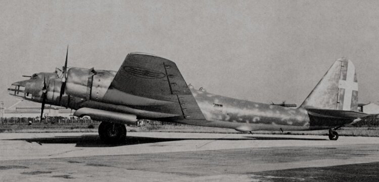 The Piaggio P.108 Bombardiere was an Italian four-engine heavy bomber that saw service with the Regia Aeronautica during World War II. The prototype first flew on 24 November 1939 and it entered service in 1941. It was one of a handful of Italian combat aircraft that could match the best manufactured by the Allies. Four versions of the P.108 were designed, but only one, the P.108B bomber, was produced in any quantity before the armistice. The other variants included the P.108A anti-ship aircraft with a 102 mm (4 in) gun, the P.108C, an airliner with an extended wingspan and re-modelled fuselage capable of carrying 32 passengers, and the P.108T transport version designed specifically for military use. Only one P.108A and 24 P.108Bs were built. The combined total number of all versions (and prototypes) was at least 39, almost certainly more than 44. Most of the P.108Cs were subsequently modified for use as military transport aircraft and could accommodate up to sixty passengers.[5] Nine P.108 Ts were used by Luftwaffe transport units until the end of the war. Number built 36 + 1 prototype (P.108B bombers); 12 + 1 prototype (P.108T transport) For details of design and development of the variants, click here.1 point
 -
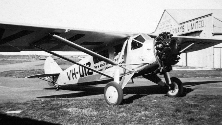 The Ryan Brougham was a small single-engine airliner produced in the United States in the late 1920s and early 1930s. Its design was reminiscent of the M-1 mailplane first produced by Ryan in 1926, and like it, was a high-wing, strut-braced monoplane of conventional design. The plane was named by Tom Mathews after Henry Brougham, 1st Baron Brougham and Vaux, designer of the Brougham (carriage). Unlike the M-1, the Brougham had a fully enclosed cabin for the pilot and four passengers. The Brougham prototype was derived from the later M-2 and was powered by a 150 hp Hispano-Suiza 8 water cooled inline V8 engine. Originally priced at $12,200, the price was reduced to $9,700 when fitted with a Wright J-5, and $5,750 with Hispano. One Brougham was fitted with floats. The only common parts shared with the famous Spirit of St. Louis and the first Ryan B-1s were the tail surfaces and a few of the wing fittings. Later B-1 Brougham production versions shared no common parts. Welded Chrome moly steel tubing was used to make the fuselage. Wood was used for the wing, but did not have and dihedral or angle of incidence. The first production B-1 Brougham was The Gold Bug, flown by Frank Hawks. It was preceded by three Hisso Broughams. Charles Lindbergh had come to the factory to examine that first B-1, but had instead ordered a completely new aircraft to his specifications. He used the Ryan NYP Spirit of St. Louis on his record-breaking transatlantic flight of 1927. Hawks renamed his B-1 "Spirit of San Diego" and flew to Washington with his wife to greet the triumphant Lindbergh. In the ensuing glare of publicity, Hawks was hired by the Ryan Aircraft company to be its official representative. With the public idolizing Lindbergh, Hawks toured the country, selling rides in the aircraft "like Lindy flew." His Spirit was actually painted gold, but looked the part to the public. Another reason for the success of the Brougham was its performance at the 1927 National Air Races in Spokane, Washington where Hawks, who had obtained a contract with Maxwell House Coffee, with the now renamed "Miss Maxwell House" came in first for speed in the Detroit news Air Transport Speed and Efficiency Trophy Race. Later, at the 1928 Ford Tudor Reliability Trial and Air Tour, Hawks placed sixth in "Miss Maxwell House". Hawks popularized the type, which stimulated demand among small airlines and charter operators. The Brougham not only sold well in the domestic market, but was exported to China, Guatemala, Mexico and Salvador. Production peaked at 20 per month but was eventually halted by worsening economic conditions in the United States that led to the sale of the Ryan factory in October 1930. Lindbergh's successful trans-Atlantic flight led to a slightly modified Ryan Brougham being ordered for the first attempted trans-Tasman flight between Australia and New Zealand. Named Aotearoa, the Māori name for New Zealand, and crewed by New Zealanders Lieutenant John Moncrieff and Captain George Hood, the aircraft left Richmond near Sydney on 10 January 1928, on a flight expected to take about 14 hours. Radio signals were heard from the plane for 12 hours before abruptly ceasing. The aviators failed to arrive in New Zealand, and no trace of them or their aircraft has ever been found. Variants B-1 - initial production version with Wright J-5 engine (ca 150 built) B-2 - one-off version with extended wingspan for Charles Lindbergh promotional tour (1 built) B-3 - version with roomier cabin, sixth seat and larger tail (9 built) B-5 - production version with Wright J-6 engine (61 built) B-7 - version with Pratt & Whitney Wasp engine (8 built)1 point
 -
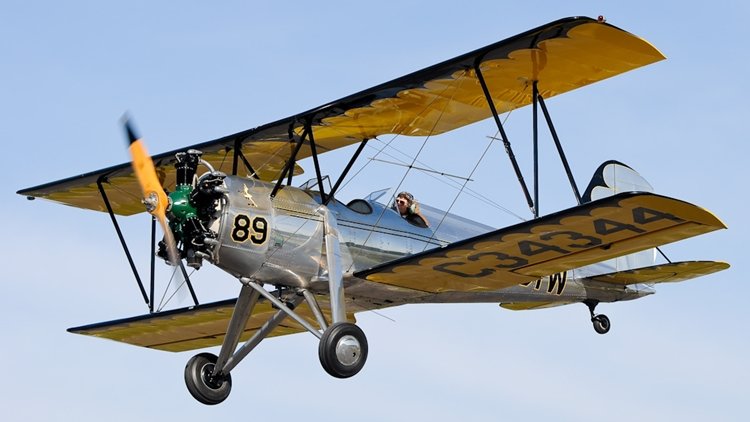 The Meyers OTW (Out To Win) was a 1930s United States training biplane designed by Allen Meyers and built by his Meyers Aircraft Company from 1936 to 1944. In anticipation for a demand for training aircraft caused by the introduction of a civilian war training scheme (in which civil flying schools would provide primary training for the military), Allen Meyers designed the OTW and formed the Meyers Aircraft Company to build it. The OTW was a conventional biplane with tandem seating for two in open cockpits and a fixed tailwheel landing gear. The prototype was powered by a 125 hp (93 kW) Warner Scarab engine and it first flew on 10 May 1936. The aircraft was produced in two main variants; the OTW-145 powered by a 145 hp (108 kW) Warner Super Scarab, and the OTW-160 powered by a 160 hp (119 kW) Kinner R-5 engine. A total of 102 were built. Variants OTW-125 Production variant with 125hp (93kW) Warner Scarab engine. OTW-145 Production variant with 145hp (108kW) Warner Super Scarab engine. OTW-160 (Specifications below) Final production variant with 160hp (119kW) Kinner R-5 engine. OTW-KR One aircraft was re-engined with a 120hp (89kW) Ken-Royce 7G engine.1 point
 -
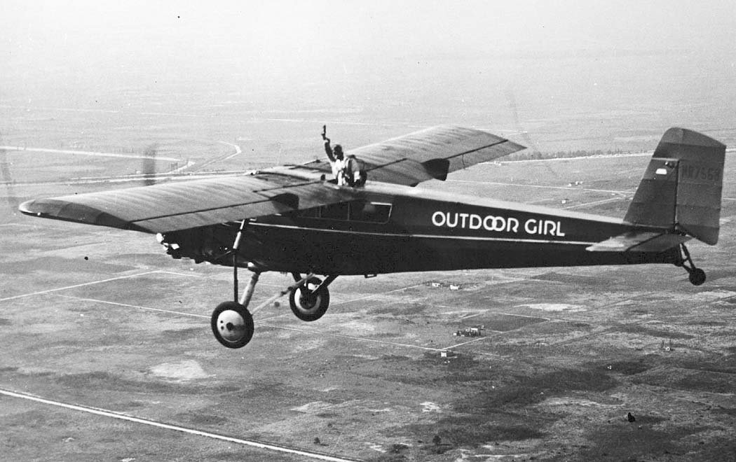 The Curtiss/Curtiss-Robertson Model 56 Thrush was a 1929 six passenger high-wing fixed undercarriage single-engine cabin monoplane airliner and utility transport powered by either a Curtiss Challenger or a Wright Whirlwind radial engine and built as an enlargement of the earlier Curtiss Robin. Several were used for record breaking endurance flights by female pilots during the early 1930s including one in which the aircraft stayed aloft for almost ten days. Three 170 hp (130 kW) Curtiss Challenger-engined Curtiss Thrush prototypes (serialled G-1 to G-3) were built at Curtiss' Garden City factory, but these were underpowered and production examples, redesignated Thrush J (serialled 1001 to 1010) with 225 hp (168 kW) Wright Whirlwind engines, were built at the Curtiss-Robertson St Louis factory. All three prototypes were later re-engined with Whirlwinds to make them Thrush Js. The fuselage of the Thrush formed the basis for the twin-engine Curtiss Kingbird which was developed roughly in parallel. The fuselage was built up as a Pratt truss frame formed mainly from Duraluminum tubing and fittings with welded Chrome-moly tubing reinforcing highly stressed areas and covered in fabric. The wing was a fabric covered semi-cantilever braced with steel tube struts, and had solid spruce spars and stamped Alclad ribs with Alclad sheet wrapped over leading edge. A fuel tank is mounted within each wing near the root. Rudder and elevators were welded chrome-moly steel tubing. 116" track undercarriage is fitted with oleo-pneumatic shock obsorbers and Bendix brakes, and is braced to the front struts and lower longerons. Noumber built: 13. Variants Thrush (ATC 159 & 160) - prototypes powered by 170 hp Curtiss Challenger, three built, all converted to Thrush J (ATC 236). Thrush J (ATC 261) - main production variant with 225 hp Wright J-6-7 Whirlwind, 10 built. Thrush Special - one converted from a Thrush J with 240 hp Wright J-6-7 Whirlwind. and a second converted with Wright J-5.1 point
 -
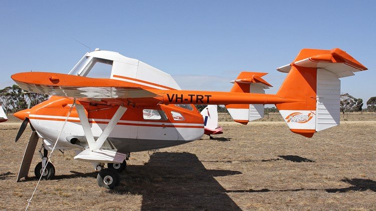 The Transavia PL-12 Airtruk is a single-engine agricultural aircraft designed and built by the Transavia Corporation in Australia. The Airtruk is a shoulder-wing strut braced sesquiplane of all-metal construction, with the cockpit mounted above a tractor-location opposed-cylinder air-cooled engine and short pod fuselage with rear door. The engine cowling, rear fuselage and top decking are of fibreglass. It has a tricycle undercarriage, the main units of which are carried on the lower sesquiplane wings. It has twin tail booms with two unconnected tails. Its first flight was on 22 April 1965, and was certified on 10 February 1966. A Transavia PL-12 featured in the 1985 movie Mad Max Beyond Thunderdome. It was developed from the Bennett Airtruck designed in New Zealand by Luigi Pellarini. It has a 1 tonne capacity hopper and is able to ferry two passengers as a topdresser. Other versions can be used as cargo, ambulance or aerial survey aircraft, and carry one passenger in the top deck and four in the lower deck. The Airtruk is also sometimes known as the Airtruck. Because the name "Airtruck" was registered by the New Zealand companies Bennett Aviation Ltd and Waitomo Aircraft Ltd, for their PL-11, Transavia found another name for their PL-12 ("Airtruk"). July 1978 saw the first flight of an improved model, the T-300 Skyfarmer, which was powered by a Textron Lycoming IO-540-engine. This was followed in 1981 by the T-300A with improved aerodynamics.[2] Transavia ceased production of the T-300 in 1985. In 1982 certification was undertaken to enable sales in the North American market. Assistance was provided by the Aeronautical Research Laboratories (ARL) of the Defence Science and Technology Organisation (DSTO) and extensive tests carried out on the ground and in subsequent flight flutter clearance trials. ref. DSTO Structures Tech. Memo. 341 In 1985 an extended version was produced and released as the T-400. The engine was changed from a 6-cylinder to an 8-cylinder and the tail booms extended by 750 millimetres (30 in). Other minor changes were made to the aerodynamics. Flutter clearance tests were again carried out by ARL and manufacture proceeded. An isolated flutter incident was reported in 1986 involving violent oscillations of the rudder and tail boom on the T-400 during a delivery flight. Investigations were carried out by ARL and a split mass balance arm was fitted to each rudder. Prior to this the aircraft had relied on frictional damping provided by the lengthy control cables. The modified aircraft was tested both on the ground, and in flight trials in March 1988 over Port Philip near Melbourne, Australia. All attempts to induce the oscillations showed that there was no indication of a mode of vibration becoming unstable. The maximum speed achieved was 160 knots (180 mph; 300 km/h) in a steep dive. Oscillations were induced with an air operated tool fitted with an out-of-balance rotating mass. This device had a rotational speed from 18 Hz down to zero for each charge of the compressed air cylinder. At least 120 had been built by 1988. For operatios,survivors and variants, click here.1 point
 -
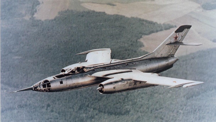 The Yakovlev Yak-28 (Russian: Яковлев Як-28) is a swept wing, turbojet-powered combat aircraft used by the Soviet Union. Produced initially as a tactical bomber, it was also manufactured in reconnaissance, electronic warfare, interceptor, and trainer versions, known by the NATO reporting names Brewer, Brewer-E, Firebar, and Maestro respectively. Based on the Yak-129 prototype first flown on 5 March 1958, it began to enter service in 1960. The Yak-28 was first seen by the West at the Tushino air show in 1961. Western analysts initially believed it to be a fighter rather than an attack aircraft—and a continuation of the Yak-25M—and it was designated "Flashlight". After its actual role was realized, the Yak-28 bomber series was redesignated "Brewer". The Yak-28 had a large mid-mounted wing, swept at 45 degrees. The tailplane set halfway up the vertical fin (with cutouts to allow rudder movement). Slats were fitted on the leading edges and slotted flaps were mounted on the trailing edges of the wings. The two Tumansky R-11 turbojet engines, initially with 57 kN (12,795 lbf) thrust each, were mounted in pods, similar to the previous Yak-25. The wing-mounted engines and bicycle-type main landing gear (supplemented by outrigger wheels in fairings near the wingtips) were widely spaced, allowing most of the fuselage to be used for fuel and equipment. It was primarily subsonic, although Mach 1 could be exceeded at high altitude. Total production of all Yak-28s was 1,180. The aircraft is perhaps best known for the heroic actions of Captain Boris Kapustin and Lieutenant Yuri Yanov after the Yak-28 they were piloting suffered a catastrophic engine malfunction on 6 April 1966. They were ordered to divert to attempt a landing in Soviet zone of Germany, but lost control of the aircraft and strayed into the airspace of West Berlin. The crew managed to avoid a housing estate but crashed into Lake Stößensee without ejecting. Their bodies, along with the wreckage, were raised from the lake by Royal Navy divers (flown in from Portsmouth) and salvage specialists, who also retrieved important top secret material from the plane. This included the engines, which were taken to RAF Gatow to be inspected by RAF and American engineers. The bodies of the two pilots were returned to the USSR with full military honors from both Soviet and British armed service members, and they were both posthumously awarded the Order of the Red Banner. The first engine was recovered on 18 April 1966 and the second a week later; both engines were returned to the Soviets on 2 May 1966. The Yak-28P was withdrawn in the early 1980s, but trainer and other versions remained in service until after the fall of the Soviet Union, flying until at least 1992. The reconnaissance and ECM aircraft were eventually replaced by variants of the Sukhoi Su-24. For details of the 20 variants, click here.1 point
 -
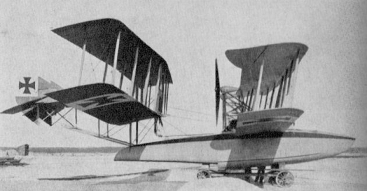 The Oertz W 6 "Flugschoner" or "Flying Schooner" with tandem biplane wings and twin chain driven propellers powered by two Maybach engines in the hull. Information on this aircraft is difficult to come by. From a Russian website: The pusher propellers powered by two Maybach 240 PS (Hp) engines. The pusher propellers were mounted on a separate construction just behind the front wing. Although the machine was not very succesfull it was acquired by the German Marine under Number 281. The other Oertz flying boats were very elegant conventional biplane machines, this was the one out of the box. Probably another designer who wanted to try something a little different. At a later date mid-wing ailerons were fitted to the rear pair of wings to improve lateral control.1 point
 -
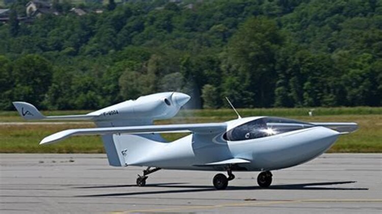 While the Lisa Akoya meets most of the LSA specifications, it is not an aircraft for the average recreational pilot or member of this forum. For a 480,000 euro (A$716,000) single engine, two seat aircraft, it's a bit rich for those other than the Elon Musk/Jeff Bezos group. The LISA Akoya is a French single-engine light aircraft, seating two in side-by-side configuration. It is an amphibious aircraft capable of alighting on land, water or snow without adaptation. It has a high-aspect-ratio electrically-folding wing, with trailing edge extensions rather than flaps, and a rear-mounted tractor configuration engine. The LISA Akoya (Akoya is a species of pearl oyster) is an innovative light aircraft designed to operate from land, water or snow without adaptation and incorporating a wing of variable area. Some other features are also unusual: it has a wing which folds for transportation by horizontal rotation through almost 90° and a single engine mounted high on the fin in tractor configuration. It is built entirely from carbon-fiber-reinforced polymer composites. The cantilever wings of the Akoya have an aspect ratio of about 18:1, very high for a powered aircraft. They have constant chord apart from the angled tips. Instead of conventional hinged flaps, the inner 2⁄3 of the trailing edge can be extended rearwards, exposing new fabric surface stored within the wing in roller blind fashion. Fully extended for landing and half extended for take-off, these surfaces provide a large increase in wing area. Conventional ailerons are fitted outboard. High mounted, the wings attach at a rotatable fairing on the highest point of the fuselage, allowing the rotation for storage. The fin and rudder together form a swept, short and parallel chord surface which carries at its top both the tailplane in T-tail configuration and the engine. The tailplane, like the wing, is of high aspect ratio and has full span elevators. The engine is a 73.5 kW (98.6 hp) Rotax 912 ULS flat four, driving a three bladed tractor propeller. The Akoya's fuselage is pointed at the nose and almost circular at its greatest diameter. In elevation it has a curved underside and, above, the large one piece canopy over the side-by-side, dual control cabin forms an unbroken line with the fuselage. There is an electrically operated retractable undercarriage of the taildragger variety, with the main gear legs rotating backward and inwards into the fuselage, and the tailwheel arm rotating forward. All wheels have hydraulic brakes. Operation from water, without a planing bottom or floats, is performed undercarriage up on the round fuselage underside with the aid of a pair of fixed hydrofoils, called shark-fins, sharply tapered planes set at about 50° to the vertical just outboard of the mainwheels. Small tip floats are an option for better lateral stability on water. The Akoya, it is claimed by the manufacturer, can also land on snow, though skis are an option. For more information on development and operational history, click here. And for the mega-rich,1 point
 -
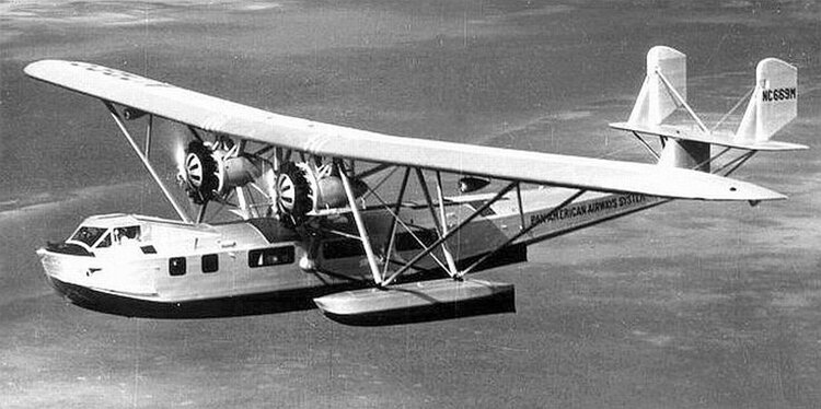 The Consolidated Commodore was an American flying boat built by Consolidated Aircraft and used for passenger travel in the 1930s, mostly in the Caribbean, operated by companies like Pan American Airways. A pioneer of the long-haul passenger aircraft industry, the Commodore "Clipper" grew out of a Navy design competition in the 1920s to create an aircraft capable of nonstop flights between the mainland of the United States and Panama, Alaska, and the Hawaiian Islands. In response to these requirements, Consolidated produced the prototype XPY-1 Admiral, designed by Isaac M. Laddon, in January 1929. Consolidated lost out on the contract to produce the airplanes for the navy to the Glenn L. Martin Company. Martin produced one prototype XP2M and nine production P3Ms. The aircraft represented a marked change from earlier patrol boat designs such as the Curtiss NC. In response to losing the Navy contract, Consolidated offered a passenger-carrying version of the XPY-1, which became known as the Commodore. A parasol wing monoplane with all-metal hull, it could accommodate 32 passengers and a crew of three. The full complement of passengers, located in three cabins, could be carried only on relatively short route segments. For a 1000-mile flight, the boat probably could accommodate no more than 14 people including the crew. Wing and tail construction consisted of a metal frame structure covered with fabric, except for metal-covered leading edges. The Commodore had significant changes from the XPY-1. These included more powerful engines, fuselage shape and structural improvements. With a first flight in 1929, a total of 14 Commodore boats were built. Starting February 18, 1930 Commodores were flown by the New York, Rio, Buenos Aires Line from the United States to South America where routes extended as far south as Buenos Aires, a distance of 9000 miles from Miami. One testimony to the Commodore in Pan Am service was made by a Pan Am pilot, Marius Lodeesen who wrote " . . . the good old Consolidated Commodore was the most reliable, trusty air craft of the Pan American fleet during the early 1930s. . . . She was hoisted aloft by two engines. They must have been Pratt and Whitneys because they never gave any trouble. . . Waterlooping the Commodore was impossible. Making a bad landing in her was hard work. She was the loveliest boat I ever flew." As the 1930s progressed the Commodores were gradually superseded by more efficient aircraft such as the Sikorsky S-42, Martin 130, and Boeing 314. A number of them went on to serve with other operators. The Commodore may be considered a first step in the United States along a road that was to lead to the highly efficient monoplane-type patrol and transport flying boats later in the 1930s. The XPY-1 and its civil counterpart, the Commodore, may be considered progenitors in a series of flying boat developments that led to the famous Consolidated PBY Catalina of World War II fame. Variants Model 16 Up to 18 passengers and three crew. Model 16-1 Up to 22 passengers and three crew. Model 16-2 Up to 30 passengers and three crew.1 point
 -
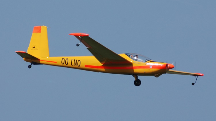 The Aerotechnik L-13 Vivat is a metal two-seater motorglider built in series from 1975 to 1999 in the Czech Republic . Designed by Karel Dlouhy, it is a side-by-side two-seater using the wings (without the flaps but with the airbrakes), the empennages and the rear part of the fuselage of the famous LET L 13 Blanik glider . The central and forward parts of the fuselage have been modified to accommodate a side-by-side cockpit covered with a one-piece molded canopy rising towards the rear and a 60 hp Walter Mikron IIIAE engine driving on the prototype a propeller in Hoffman fixed pitch wood. The aircraft is based on a single-track undercarriage (a retractable fork in the fuselage and a fixed rear castor) and roller topping lifts at the wingtip that rise under the salmon in flight. The first mass-produced version in 1975 ( L-13SW Vivat, later renamed L-13SEH ) gave rise to several versions, details of which can be found below. Around 200 examples were built, with more than 150 exported worldwide. Evektor ceased production of this aircraft in 1999 to concentrate on manufacturing Eurostar two-seaters . Variants L-13SE Vivat: Only model fitted with flaps, Mikron IIIAE engine. L-13 SEH Vivat: Standard model (ex L-13SW ) with Mikron IIIAE engine driving a three-position Hoffman propeller. L-13SL Vivat: Standard model with 67 hp Limbach L200E01 engine driving a constant speed Muhlbauer propeller. L-13SDLiva Vivat: Version of the previous one equipped with a classic fixed main landing gear, with removal of the topping lifts. L-13SDM Vivat: Model with Mikron IIIAE engine equipped with a conventional fixed main gear.1 point
 -
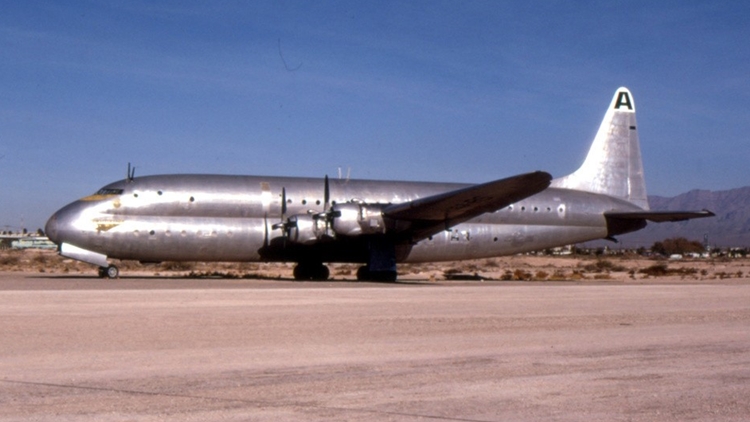 The Lockheed R6V Constitution was a large, propeller-driven, double-decker transport aircraft developed in the 1940s by Lockheed as a long-range, high-capacity transport and airliner for the U.S. Navy and Pan American Airways. Only two of the aircraft were ever built, both prototypes. Although these two planes went into service with the Navy, the Constitution design ultimately proved underpowered and too large for practical airline use at the time. Although the Martin JRM Mars flying boat had a slightly longer wingspan, the Constitution remains the largest fixed-wing aircraft type ever operated by the U.S. Navy. The Lockheed Constitution began life in 1942 as a joint study by the U.S. Navy, Pan Am, and Lockheed. The design requirements, initially designated Lockheed Model 89, called for a large transport aircraft to improve upon the Navy's fleet of flying boats. Pan Am was involved in the study because such an aircraft had potential use as a commercial airliner. This transport would carry 17,500 lb (7,900 kg) pounds of cargo 5,000 miles (8,000 km) at a cruising altitude of 25,000 feet (7,600 m) and a speed greater than 250 mph (400 km/h). The aircraft would be fully pressurized and large enough so that most major components could be accessed and possibly repaired in flight. For instance, tunnels led through the thick wings to all four engines. The aircraft was designed by a team of engineers led by Willis Hawkins and W.A. Pulver of Lockheed and Commander E. L. Simpson, Jr. of the Navy. The name Constitution was given to the project by Lockheed president Robert E. Gross. The Constitution design had a "double bubble" fuselage, the cross section of which was a "figure eight". This unorthodox design, originally created in 1937 by Curtiss-Wright's chief aircraft designer George A. Page Jr. and first introduced with the Curtiss C-46 Commando, utilized the structural advantages of a cylinder for cabin pressurization, without the wasted space that would result from a single large cylinder of the same volume. The original contract from the Bureau of Aeronautics called for 50 Constitutions for a total price tag of $111,250,000. On VJ Day, however, the contract was scaled back to $27,000,000 for only two aircraft. FGor the operational history of the two units built, click here.1 point
 -
 The Ryan STs were a series of two seat, low-wing monoplane aircraft built in the United States by the Ryan Aeronautical Company. They were used as sport aircraft, as well as trainers by flying schools and the militaries of several countries. T. Claude Ryan was the founder of the Ryan Aeronautical Company, the second incarnation of a company with this name, and the fourth company with which he had been involved to bear his name[1] (the first, Ryan Airlines, was the manufacturer of the Ryan NYP, more famously known as the Spirit of St. Louis). He began the development of the ST (for "Sport Trainer", and also known as S-T),[2] the first design of the company, in 1933. The ST featured two open cockpits in tandem in a semi-monocoque metal fuselage of two main frames – one steel, the other half of steel and half of aluminium alloy (alclad) – to take the loads from the wing spars and six more alclad frames; and alclad skin. It had wings in three sections of hybrid construction; the center section integral with the fuselage had tubular steel spars, the front spar a simple tube with an external brace to the upper fuselage, and the rear spar in the form of a parallel chord truss. The two outer wing panels had wooden spars and alclad ribs, with diagonal rods bracing the wings internally. Alclad sheet was used to form the leading edges, and fabric covered the whole structure. When attached, the outer wings were braced with flying wires to the fixed conventional landing gear and landing wires to the upper fuselage. A large number of STMs were exported in the 1930s and early 1940s (prior to the entry of the United States into World War II) to various air forces, with the biggest customer being the military of the Netherlands East Indies, now Indonesia. The Netherlands East Indies Army and Navy took delivery of 84 STM-2s and 24 STM-S2s in 1940 and early 1941. After the Japanese invasion of the Netherlands East Indies many Ryans in that country were pressed into combat, especially in reconnaissance roles, and large numbers were shot down or destroyed on the ground. Surviving STM-2s and STM-S2s that were not captured by the Japanese were shipped to Australia, where 34 entered service in the Royal Australian Air Force as trainers. Many of those that survived until the end of World War II were then placed on the civil register in Australia and elsewhere, and some are still flying more than 70 years after they were built. For more information on the development, operational history and numreous variants, click here.1 point
 -
 It was overshadowed in the public consciousness by the Supermarine Spitfire's role during the Battle of Britain in 1940, but the Hurricane inflicted 60 per cent of the losses sustained by the Luftwaffe in the engagement, and fought in all the major theatres of the Second World War. The Hurricane originated from discussions between RAF officials and aircraft designer Sir Sydney Camm about a proposed monoplane derivative of the Hawker Fury biplane in the early 1930s. Despite an institutional preference for biplanes and lack of interest from the Air Ministry, Hawker refined their monoplane proposal, incorporating several innovations which became critical to wartime fighter aircraft, including retractable landing gear and the more powerful Rolls-Royce Merlin engine. The Air Ministry ordered Hawker's Interceptor Monoplane in late 1934, and the prototype Hurricane K5083 performed its maiden flight on 6 November 1935. In June 1936, the Hurricane went into production for the Air Ministry; it entered squadron service on 25 December 1937. Its manufacture and maintenance was eased by using conventional construction methods so that squadrons could perform many major repairs without external support. The Hurricane was rapidly procured prior to the outbreak of the Second World War in September 1939, when the RAF had 18 Hurricane-equipped squadrons in service. The aircraft was relied on to defend against German aircraft operated by the Luftwaffe, including dogfighting with Messerschmitt Bf 109s in multiple theatres of action. The Hurricane was developed through several versions, into bomber-interceptors, fighter-bombers, and ground support aircraft as well as fighters. Versions designed for the Royal Navy known as the Sea Hurricane had modifications enabling operation from ships. Some were converted as catapult-launched convoy escorts. By the end of production in July 1944, 14,487 Hurricanes had been completed in Britain, Canada, Belgium and Yugoslavia. For more details of the development, design, operational history and variants, click here.1 point
 -
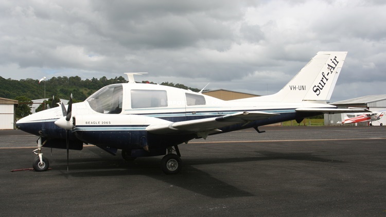 The design of a twin-engined light transport began in 1960 and the prototype registered G-ARRM (designated the B.206X) first flew from Shoreham Airport, West Sussex on 15 August 1961. The prototype aircraft was a five-seat all metal low-wing monoplane powered by two Continental flat-six engines. The second prototype (registered G-ARXM and designated B.206Y) was slightly larger with a larger-span wing and seating for seven. Initial production was the Series 1 aircraft which were powered by 310 hp Rolls-Royce Continental GIO-470A engines, and the first aircraft (G-ASMK) first flew on 17 July 1964. This aircraft was then converted as the first Series 2 aircraft with 340 hp Continental GTSIO-520C turbocharged engines and first flew as such on 23 June 1965. The production Series 2 (initially known as the B.206S) was also fitted with a large freight door. The aircraft was soon in demand with air taxi companies and as a light transport for companies. Three aircraft were delivered to the Royal Flying Doctor Service in Australia. For more details, including the seven variants, click here. Specification below are for the B.206 Series 2 variant.1 point