

skippydiesel
-
Posts
7,622 -
Joined
-
Last visited
-
Days Won
73
Content Type
Profiles
Forums
Gallery
Downloads
Blogs
Events
Store
Aircraft
Resources
Tutorials
Articles
Classifieds
Movies
Books
Community Map
Quizzes
Videos Directory
Posts posted by skippydiesel
-
-
4 hours ago, Marty_d said:
Oh, that's a good idea.
I thought cabin heat usually came from a muff around the muffler itself, but taking it off an exhaust pipe makes sense.
It seems to me, if using the exhaust heat (there are other option), you would take the heat from where you will get the best result (volume & temperature of hot air).
If the builders have determined that the exhaust pipe, rather than muffler will deliver what they want - all good.
Using the exhaust system to heat cabin air is the tradition method , with the known potential for CO poisoning & transmission of engine noise. Safer quieter alternatives are available.
Alternatives heat sources that seem to be viable are - Cooling System (hot liquid) Coolant Radiator (air) and Oil Cooler (air).
- The Cooling l system can be plumbed and controlled much like a car heating system but requires additional hoses, valve , small heat exchanger and fan. Likely to be relativly heavy & complex compared with the other systems. There is no chance of CO poisoning. As heating will be tied to engine temperature, may be slow to get going.
- Coolant Radiator - I have seen a design where hot air is taken from the back of the radiator & reticualted in a similar way to the exhaust heated air . The upside to this is no chance of CO poisoning. Once again may be slow to get going.
- Oil Cooler - similar to the above.
A the use of thermostats, in all of the above, would speed hot air delivery and may make the system less prone to temperature drops, when at low power (descent)😈
-
 1
1
-
13 hours ago, 440032 said:
Plan B.
Fit a FUMOTO oil drain valve, once.
I see this idea promoted quiet a lot on the Rotax Owners Forum.
Cant see the need myself. At the rate I accumulate hr's an oil drain only happens once per annum, in a good year a possible second. Hardly a challenging workload.
The drain plug should not be tightened any more than necessary to crush the washer (Rotax will have some ridiculously low torque setting , wrist "click" will do me)- easy to see & do. The plug is then safety wired to the base of the tank. - no chance of comming undone.(I have never had a leak from the oil tank).
Removal is a doddle - remove safety wire and using two spanners "crack" the lightly torqued plug.
Its now finger tight but a tad hot to actually use the fingers, so continie to loosen with one spanner.
Put your old oil receiveal container up as close to the bottom of the tank, as is constant with doing the job/access - this will reduce the chances of spillage.
I use roofers soft aluminium flashing (Bunnings Aerospace) formed into a channel & hooked over the engine frame, to direct the oil into a calibrated container (I like to record oil quantity removed, then added).
It's annoying but of little concern if the plug drops into the hot oil - magnet will fish it out.
I am not against the oil drain valve - have one fitted to my Ranger sump. The Ranger requires removal of bash plates, before loosening the drain plug and then the position of the drain means oil hits a cross chassis member & splashes everywhere (nasty!). The drain valve & short hose prevents, all that mess & the need to remove bash plates- a no brainer!😈
-
1
-
-
Thanks Thruster,
Will look into the Silicon tubing, looks promising. As you suggest, IF it is a tight fit, security clamping at just one end may be acceptable.
Float bowl breather tubes are plumbed into the airbox (same air pressure at carby inlets). The airbox has drains that exit into a temporary catch can, so that any fuel leak can be monitored.😈
-
 1
1
-
-
24 minutes ago, 440032 said:
Plan B.
Fit a FUMOTO oil drain valve, once.
I see this idea promoted quiet a lot on the Rotax Owners Forum.
Cant see the need myself. At the rate I accumulate hr's an oil drain only happens once per annum, in a good year a possible second. Hardly a challenging workload.
The drain plug should not be tightened any more than necessary to crush the washer (Rotax will have some ridiculously low torque setting , wrist "click" will do me)- easy to see & do. The plug is then safety wired to the base of the tank. - no chance of comming undone.(I have never had a leak from the oil tank).
Removal is a doddle - remove safety wire and using two spanners "crack" the lightly torqued plug.
Its now finger tight but a tad hot to actually use the fingers, so continie to loosen with one spanner.
Put your old oil receiveal container up as close to the bottom of the tank, as is constant with doing the job/access - this will reduce the chances of spillage.
I use roofers soft aluminium flashing (Bunnings Aerospace) formed into a channel & hooked over the engine frame, to direct the oil into a calibrated container (I like to record oil quantity removed, then added).
It's annoying but of little concern if the plug drops into the hot oil - magnet will fish it out.
I am not against the oil drain valve - have one fitted to my Ranger sump. The Ranger requires removal of bash plates, before loosening the drain plug and then the position of the drain means oil hits a cross chassis member & splashes everywhere (nasty!). The drain valve & short hose prevents, all that mess & the need to remove bash plates- a no brainer!😈
-
 1
1
-
-
1 hour ago, Thruster88 said:
I don't see the down side with ditching the cold air intake and going pod filters. Very slight loss of power at full throttle but how often is that used. For any part throttle operation the throttle just has to be a little more open to compensate for the less dense warmer air. I see coolant carburetor heaters so carb ice should not be a problem.
If anything the airbox arrangement makes carby ice more likly, than conical filters sucking warmed air. As you noted, the manifold heaters (claimed to prevent icing) are part of the existing system. My last 912 with just conical filters, never even hinted carby icing. (This is not a claim that Rotax 912's do not experince carby ice)
When I was trying to isolate the cause of my leaking carby bowl breathers, I ran the Rotax conical (pod?) filters - no leak.
Hot inlet air, will have some (?) performance loss implications. I agree, likly small, however this is not the only consideration. A lot of work & cost, went into the existing air box. One of my flying objectives - economical (fuel used for NM covered) touring, so no unnecessary fuel consumed (throttle setting). Together ,this means that it would take a genuine safety or performance issue, for me to ditch the airbox.
The photo I posted was of the unfinished item - now looks a lot more professional, sporting a black satin look, heat resistant, ceramic, finish.
I have no complaints about the airbox performance - now that it's not using the carbys for part of its support system. The clearances, due to limited space, is a minor problem that only impacts on my choice of airbox to carby duct, the topic of this thread /discussion😈
-
BurniM & RossK,
Looks like the same iPad bracket that I had in the Zephyr - worked well.
I did modify it a bit, by drilling extra holes in the back to facilitate better air flow from the eyeball vent - don't actually know if this improved things or not, as the fitting of a dedicated vent coincided with cooling mods - no further overheating occured.
I don't like suction mounting systems - they seem to pick just the wrong moment to let go. I do use them to place the device (?) in various locations around the cocpit, decide on the best, install a fixed ball for security.😈
-
1
-
-
2 minutes ago, Thruster88 said:
Is the airbox mounted to the engine or the airframe? Given the way your engine is mounted, it obviously moves a fair bit at times. Is there a risk your airbox could pull a carb out of its socket?
Alot of rotax installations just have a pod filter on each carb, simple, light weight and it must work.
Originally the airbox was mounted/supported on engine & both carbys - far too rigid.
As you may know the carbys have a "rubber" inlet manifold section, specifically to minimise the effects of engine vibration & movement on the carbys. The above arrangement was effectively negating this system.
The airbox now has two supports on engine itself - one a vibration isolator, the other a saddle - the idea being the airbox weight is no longer on the carbys but still moves with the engine.
Not sure but think the Rotax OM airbox & ring gear are attached. The airbox is far enough back from the carbys to have a longer /more flexible connecting duct/hose.
To minimise the potential for restricting the inlet manifold rubber flexing a very flexible duct/hose between carby and airbox needed to be found.
SCAT, with wire in place, was tried however the small gap (10-15mm) between airbox & carby meant that the wire effectively removed the ability of the two fixtures to move independently. Removing the wire solved that problem.
I do not believe there is a risk of the existing modified SCAT comming adrift - I have had one significant engine start/movement event - duct stayed in place.
My last aircraft ATEC Zephyr, used the two conical Rotax filters - worked well. (Maxed out at about 125 Kt - Normal /Eco Cruise 100-110 Kt Indicated)
The Sonex is a significant step up in performance - outside/cool air supply to the engine, is part of this. (Max Cruise 152 Kt True - Normal/Eco Cruise 130 Kt True)😈
-
1
-
-
Onetrack,
"......airbox that doesn't have a satisfactory connection arrangement to the carburettors."
Satisfactory?? depends on what you mean. The solution I have works, it's just not as elegant as I would like.
As a whole the engine installation, is what it is - it actually works very well - not perfect but then what is?
The not insurmountable problem (carby to air box ducting) is "chicken feed" in the scheme of homebuilt problems that can arise. I have a working fix that has served successfully or about 100 hrs now. I did replace it at the 200 hrs service , as I don't know how durable it may be over time. Certainly I would like a better fix - a durable hose/duct similar to SCAT but without the reinforcing wire. I don't like modifying the SCAT - I am concerned by the potential for damaging the fabric and the much lesser esthetic result (looks unprofessional)
As mentioned earlier, Sonex have recently come up with a Rotax 912 adaptable "ring mount" engine , which would likly result in a far better/more space in the engine bay - way to late for my build which has now been flying for 200 Hobbs hours.😈
-
1
-
-
24 minutes ago, onetrack said:
Agree. I'd start by redesigning that mongrel-looking airbox.
It actually works very well - Appearances, lack of convention, whatever is spurring you to make negative commentary, is jumping to a conclusion that you have no practical basis for.
Quote-
 1
1
-
-
1 hour ago, BurnieM said:
I am confused why this ducting is required.
I would have thought you already have ducting from the outside air to the airbox and airbox to carb. What are you hoping to achieve. Can this be achieved by modifying the existing ducting ?
Hi BurnieM,
I apologise if I didnt not articulate my need in a more comprehensive manner.
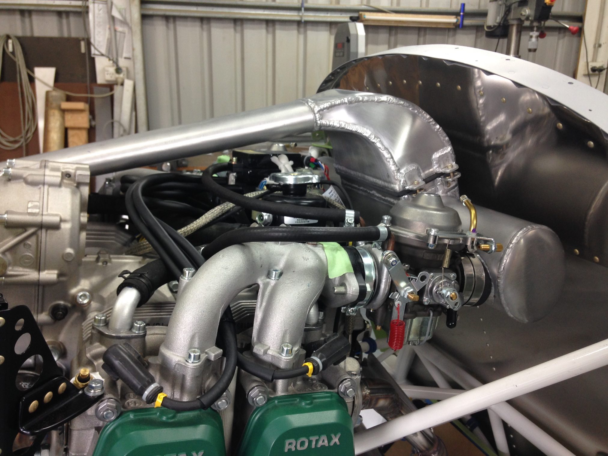
My airbox is a home made unit. It features a forward facing "horn" to the front R cowl inlet (fresh, cool, possibly pressurised air)
My Rotax 912ULS is installed in a Sonex using an Aerovee/Rotax adapter - makes for very tight engine to firewall space (Sonex have recently come up with a Rotax style "ring mount".)
The duct that I am discussing is between airbox & carburettors.
The space between carby inlet & airbox outlet, is about 10-15mm (not counting the mounting flanges ).
Previous ducting was a thick walled "rubber" hose.
I had a problem with the carby's ejecting fuel, from the float bowl, through the bowl breather.
After much trial, error & debate (mainly on Rotax Owners Forum) the fuel problem narrowed to the carby vibration/movement isolators being impeded by the connection to the airbox.
The solutions; # Take all airbox weight off carby(s) # Fit a more flexible duct between airbox/carby, has worked.
The more flexible duct, I am currently using is the aforementioned, modified (wire removed) SCAT .
The wire removal damages the fabric. Great care is need to avoid punctures (wastage). After wire removal the surface looks a bit tatty & may have been weakened.
My only reason for raising this topic is in the hope that someone can recomend a SCAT like ducting, that would deliver a better more durable finished product.😈
This is a build stage photo (now has Hobbs 200hrs) shows test fit of airbox & inlet "horn" Note: how close air box flange to carby flange.

-
2
-
-
It could be my imagination - have we come full circle back to RAM Mounts.
I had one for my iPad in the Zephyr. Went "out" on overheat twice (in winter) before I fitted a dedicated eyeball vent, delivering cool outside air to the back of the cradle/ipad.
I now have one in my Sonex, for my back up GPS - if need be can be cooled by Pax vent. The iPad is in a fan cooled dock on the panel.
The iPad panel dock looks the goods/professional but is actually not as adaptable as the RAM system, which can be adjusted to suit the pilots or pax view but for reading issues like glaire. .
😈
-
13 hours ago, BrendAn said:
silicone radiator hose?
Possible.
All the silicon hose, I have seen, is pretty thick walled/heavy stuff - I doubt a 10-15mm gap would allow much movement.😈
-
1
-
-
Moneybox,
"I I did see somewhere it mentioned up to 20kt cross wind."
A 20Kt X wind component would be unusually high for small aircraft like yours.
Your POH states 10Kt for TO/Landing. I would go with this and not try to "explore the envelope" in what can be a challenging flight situaton, with very little room for error.
The most challenging X wind is a blustery one, it's there, then gone, then back - the pilot is fighting to mainatine straight & level while slipping on/of, into wind - not fun!
Aircraft types may have very diffrent handling characteristics, in X wind landings, from relativly benign to scary. 😈
-
3
-
1
-
-
18 minutes ago, Blueadventures said:
That's how it is 95% of the time, when clear too many visual references can be seen so hard to find the right heading without compass or the GPS aides.
Please expand - particularly on ".......so hard to find the right heading without compass or the GPS aides."
No offence but it reads like you may need some nav. refresher training.😈
-
40 minutes ago, BurnieM said:
I think he said earlier that he had a handheld GPS witth airfield waypoints.
So not exactly no backup.
That's great!
So why the concern about iPad / magenta line, reliability and inability to establish a heading?
I have never flown in WA, it may be a little like western NSW (where I did all my GA training).
In the pre GPS era, I was comfortable, in what the city VFR pilots called features terrain.
I moved to the Sydney Basin, had to have a local pilot with me for the first few flights - I couldn't see the landmarks for the buildings. Its what you get used to.
I was trained to take heading notes. While heading will change over time, the failure of devices (compass/heading indicator & now EFB/GPS) should not be anything more than a minor inconvenience .
The X country pilot expects not to easily recognise subtle features - fly your heading.
Horizon indistinct - fly your heading.
Your last heading, will likly get you to some feature, that will allow you to reorient (if necessary).😈
-
1
-
1
-
-
1 hour ago, Moneybox said:
That's ok when the going is smooth but a few corrugations start the compass behaving badly. That can be ok too for a bit if I have a site in the distance but on the way up here I had haze and bright sunshine making finding a long distance target difficult.
Sorry Moneybox - No excuses. If whisky compass a dud, get a new one. If OzRunways not giving heading info, reconfigure screen. Hand held (back up) GPS not very costly, in the scheme of aviation related costs. Pencil & paper is your freind.
For you & your Pax safety, some form of reliable backup(s) is essential on a navigation flight outside your usual "home" range.
Fly safe.😈
-
1
-
-
Hi Moneybox,
"I don't trust the iPad "
You shouldn't trust any device, that may let you down in flight.
That's why you have a paper flight plan, with all the necessary information to complet your flight safely.
Your flight plan should be updated, in flight, with any changes to heading, altitude or flight time, so that a failure of your EFB will have little if any effect on the continuation of your flight.😈
-
1
-
1
-
-
If you can find someone with a laser printer, they can make you amazing labels - almost any shape, colour, font, size, you might imagine.😈
-
1
-
-
11 hours ago, onetrack said:
Skippy - What level of "heat resistance" are you actually seeking? (precise temperature range). I fail to understand how you think you can acquire "thin, flexible, heat-resistant" ducting, without it having some kind of internal support.
You either have thin ducting supported internally by wire or PVC ribbing, or you have thicker wall, unsupported ducting. A thin wall is not going to support itself, that's why layflat hose lays flat.
Ha ha!
The hose/duct need not be self "supported" because the gap between the carby & airbox is only about 10mm.
Due to the short distance, the wire ribbing of the SCAT gets in the way & restricts some of the relative movement that needs to happen.
Temperature Range - From ambient Australian east coast winter, say a rare 0C, to summer, under cowl , post engine shut down 80C. In operation the undercowl temperature is a consistent +10C above ambient. The duct will be supplying outside air, from the air box to the carby(s), so there is the potential for -C (?) temperatures at altitude.😈
-
1
-
-
If such exists- SCAT, without the wire would be perfect.
Something along the style of lightweight lay flat hose. 😈
-
Thanks Onetrack,
A quick brows would suggest that the ducting is either wire reinforced (too stiff) , to large an ID or has insufficient heat range for safety.
Thanks for trying
😈
-
1
-
-
Ram Mounts are the way to go.
If you locate in front of an eyeball vent, no problems with overheating.
😈
-
1
-
-
3 hours ago, rodgerc said:
Just checking you familiar with the Rotax oil priming process utilising low pressure compressed air.
Is that a question or a statement?
If so, to whom is it directed ?😈
-
1 hour ago, onetrack said:
Corowa Recreational Flying Club has a little more information. Note that avgas is not available due to the fuel supplier withdrawing their facilities there, due to low patronage - and premium unleaded is only available by arrangement with the aforementioned club.
Speculation; I think a trip into town, would find 98 RON. Likely far cheaper than an airport mobile supply service😈
-
1
-
Midair Oakdale area 26 October 2024 - Fatal injuries reported
in Aircraft Incidents and Accidents
Posted
You are correct about the Jab - remained in circuit, after a go round.
The Cessna had departed Camden, upwind, runway 24, however that was some time before the incident ie no bearing on the incident.
A simplified / abbreviated version of events;
On Saturday morning, 26 October 2024, Weather good, although some pilots reported some turbulence - others did not.
It appears that the Jab 450 (1 pilot) & Cessna 182 (2 pilots), flying in opposite directions, in the circuit, at about circuit height (1900"), collided at about midfield, due West of The Oaks airfield. All three people died as a result of the collision.
I doubt if we will ever know;
We do know ;
There is a much longer more detailed official report - doesn't change what I have just summarised.😈