

Peasant_Pilot
-
Posts
135 -
Joined
-
Last visited
-
Days Won
4
Content Type
Profiles
Forums
Gallery
Downloads
Blogs
Events
Store
Aircraft
Resources
Tutorials
Articles
Classifieds
Movies
Books
Community Map
Quizzes
Videos Directory
Posts posted by Peasant_Pilot
-
-
Looking for a technical drawing of a type/model C karatoo wing spar and wing layout. I have an early model Karatoo A model and plans but the later model had a better spar and rib design. Happy to purchase some drawings if anyone has them
Cheers
Rob
-
in all honestly i dont have any huge attachment to the name Valkyrie but iv been considering giving it a better designation lately as its really not the same aircraft when i first started
-
yeah, she has been really helpful so far, specializes in LSA type aircraft and composite so I feel she would be the right person
-
 1
1
-
-
this is more of just a slight visual update, have made very minor adjustments and have been in initial discussions with Sonja Englert about structural development, weights etc

-
 1
1
-
 1
1
-
-
6 hours ago, RFguy said:
between- as in forward, aft of mainspar of person CoM on the spar? What's the CoG location look like with no fuel in the fuel tanks (assuming forward of mainspar) and max people and baggage ?
I see a few low wing aircraft that with nothing in the tanks(which are often forward of the mainspar) and full peeople and baggage, marginal CofG condition.
Working through that over the next few weeks to make sure it's going to work where it is. Will keep you upto date
-
Essentially sitting between the spars, seating is at 35 degrees
I'm aiming for a safe +6 - 4g's
-
2 hours ago, RFguy said:
How many sqft of wing do you have at the moment ? Lancair of course is not in the same race / category at what you are proposing , a different beast.
The Lanceair foil, type NLF-0215 is worth studying. it is a new foil from the 1980s.
Have a look at NASA technical report 1865 . (June 1981 ).. it is in there.... it isn't all plain sailing though, the super-duper airfoil is quite sensitivie to flow disruption (bumps turbulence etc etc)
https://www.n91cz.net/Interesting_Technical_Reports/NASA-81-tp1865.pdf
Retract : Cirrus does pretty well with non retract, I'd suggest same. Many small GA planes are retract just so they can be commercial trainers. Hanging around a maintenance facility, I can tell you that retractable gear systems - is probably problem child #1 and in general, never quick to solve due to the sheer numbers of joints, switches, pressure sensors, pumps, motors, relays O.M.G !!!!!
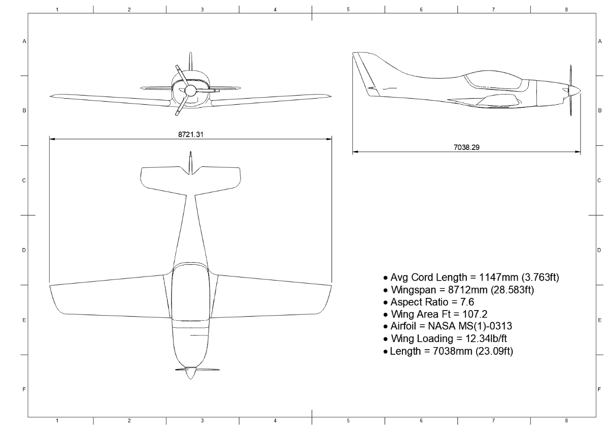
has 107 sq ft of wing area as it sits, attached is a quick spec sheet to give some more insight, and while I'm tinkering away with a retract option, ultimately it will be standard fixed tricycle. I firmly believe for RAUS it is the most suitable
-
1
-
-
the JMB VL3 has a similar tail too and to a lesser extent the WT9 Aerospool. id say it would have to work, and these planes are going quick too
-
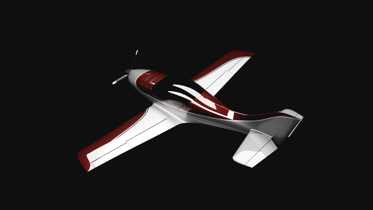
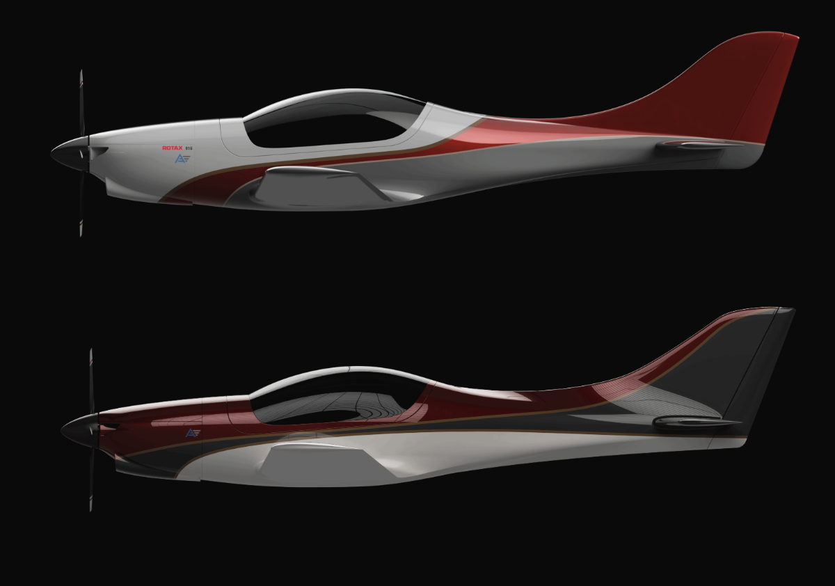
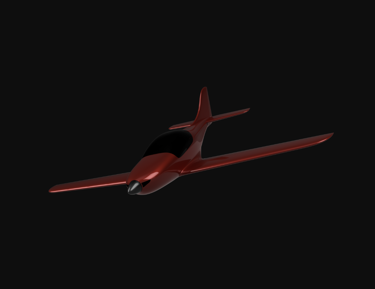
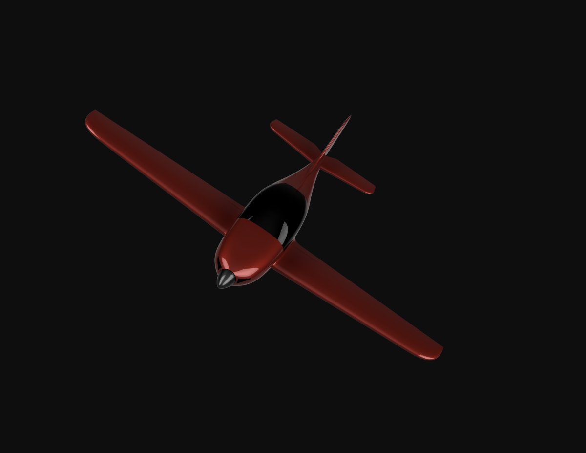
So last night I burned through the night to redesign the tail section, I've been really happy with the profile of the aircraft but I always had in my head id have to really beef up the tail section due to it being quite small in the tail end Cross sectionally, so I've incorporated the vertical stabilizer more so it's more as one structure instead of seaming like a separate entity, iv increased the size a little of the top and bottom strakes and essentially created a much stronger cross section, while I still need to get used to it, I feel this is more where it needs to be structurally. I ended up 3d printing some 10% scale tail sections of both and doing some twist tests on it and the new design was far superior in strength and resistance to twisting. Obviously, it's not the same thing but it's a proof of concept to a degree.
see in the picture the comparison to the previous design in the tail section to the new one, new design is on the bottom. ill also add in a couple of colour renders to see what you think
-
1
-
-
It's interesting, I remember reading about the Cobra Arrow, it originally had stabilators on it, but they had some issues with Pilot induced oscillation, so they switched to elevator in a later version to negate it. just had me curious
-
What are people's thoughts on stabilator vs elevator? I like things relatively traditional but I'm curious top hear people's thoughts on it
-
Quote1 hour ago, Moneybox said:
I've enjoyed a quick read through the development of the project. It's a great idea that I'd love o see come to fruit but.....
I've spent a lifetime in design, engineering, drawing and building. I'm still enjoy building things, rarely following others and usually come out with a successful article in the end. At 71 years of age now I've learned a few things along the way that would have be advantageous had I known about them before starting out but I'm not a person to easily accept advice.
Just to add my two bobs worth, some people have a great brain for concept, others design, some people are masters of fabrication and too many get carried away with technical know-it-all. Very few people can take a successful marketable project from concept to completion in a reasonable time.
I believe if you have a fabulous concept such as this you would most likely get to the climax a lot easier, cheaper and better to have various good capable people working together. One difficulty is keeping it under control if several minds wander off on their own agender but building something as complex as an aircraft needs specialists in a range of fields and very few people have to ability to achieve it alone.
A lot of good ideas die with the passage of time. If you want to get it in the air do it NOW. Pool a bit of money, get some great minds together and use people with good trade skills to build the components. Too many try to go it alone, me included, and we are usually stifled by lack of experience, time and money.
I really appreciate that, very wise words and unfortunately im a bit of a sucker for trying to do everything on my own as well , I'm actually a fabricator but have learnt design the last 2 years and very much enjoy both aspects of it. I'm going to take your advice and reach out to some people as far as development and production goes and get a few of the right people on board, i have a bit of money there to spend and i think you are absolutely right in what you have said. Probably the best advice i have had and really appreciate the informative and positive response
will keep you updated with how everything is developing
-
4
-
-
That's actually something iv wanted to do, I started out back in the day building my own rc stuff from scratch and I still very much have a soft spot for it.
I like your thinking though.....that's something I could start on pretty quickly I think.
Good to see other RC enthusiasts still kicking about
-
It's definitely a massive undertaking, and the idea might never get off the ground(no pun intended).....but the process is extremely enjoyable developing it from the ground up. learning CAD design and understanding aerodynamics and seeing the quality improvement in my work makes the effort enjoyable and worth while.
Honestly never thought I'd be capable of getting this far but I'll keep sharing progress on it.
-
3
-
-
Appreciate the interest honestly,
The stress analysis I've only been able to test on componentry, bulkheads, firewall, landing gear. as far as the airframe goes that's something I think that will have to be done and tested/experimented with once i have a test airframe built, same as for CG and so on, i can only do so much in CAD and CFD and it will be something when it comes down to vibration, flutter and twist load tests will need to get further expertise on. as far as the design goes, wing position, airfoil, aspect ratio angle of incidence, dihedral, pilot position, control surfaces, washout i have based that all of various existing aircraft I've studied and what I was wanting to achieve, I've spent countless hours going through many plans sets, talking to Engineers and trying to get everything where it needs to be but really there is a lot to be tested outside the CAD Programs
I looked at a lot of aircraft of similar size that I was wanting to design, took a bunch of measurements off aircraft like the SportStar, TL Sting, Pulsar XP, Falco, Lancair 320 etc. and have tried to work within similar bounds. started with a sketch how I wanted it to look then altered it to suit the important things
As far as performance goes, looking realistically at 120kn cruise on a tricycle config, 45kn stall all originally to run on a Rotax 912uls. wing has 1.8 degrees angle of incidence, 4 degrees on the dihedral, seating is at 35 degrees, washout is 2 degrees, around 290-310kg empty with a 912ULS, wingspan is 8.77mtr
I'm in no way an expert and am very much learning as I go and have altered the design many times to correct issues as I've developed more knowledge around it. Obviously a safe and stable aircraft is priority, but I also wanted a nice looking aircraft. I started with some reference points and designed around that.
Really, I wanted something that was a little quicker than a Sporty but still stable and easy to fly, something fitting for RAAUS 600mtow
End of the day, I'll keep changing the design until its where it needs to be structurally and aerodynamically so it's a safe and stable aircraft, but I feel it's pretty close, I think I need to actually build an airframe and refine from there, I have a few design ideas I want to try and experiment with and for me I can only really do that with a physical part/airframe.
It's pretty overwhelming sometimes but it's been educational that's for sure....and frustrating at times
Cheers
Rob
-
1
-
2
-
-
I
26 minutes ago, RFguy said:My 2c worth is
1) that common areas that might need repairs try and keep as fibreglass, or at least replaceable whole regions--- as structural carbon fibre repairs are not a beginner's pasttime....
2) consider what metal or wood ablative charing layer or fire retard on the fibreglass etc / resin you want up front such that an engine fire is survivable......
glen.
Yeah I agree 100%
While I find the cfd and stress simulation handy as a guide, there is no substitute for actual testing, I plan on having a couple of sacrificial airframes and parts for load and crash testing, fire etc etc. Gotta build the buck for the molds and then onto that
-
1
-
-
Main fuse and wing skins will be S-Glass and some carbon where needed, spars I'm looking at testing some composite ideas and a laminated hoop pine spar, xps foam and hoop pine for some of the core, wing ribs, bulkheads etc.
Using fusion 360 for the design and simscale for stress and flow analysis and will be doing physical testing on the spar and wing components etc
-
1
-
-
Pretty much all the external shaping and dimensions are done, few little jobs before undercarriage and interior, currently working through the internal structure, spars, riba and bulkheads etc.
If you have anything that youd like to see in an 600mtow aircraft, let me know, always open to it
-
1
-
1
-
-
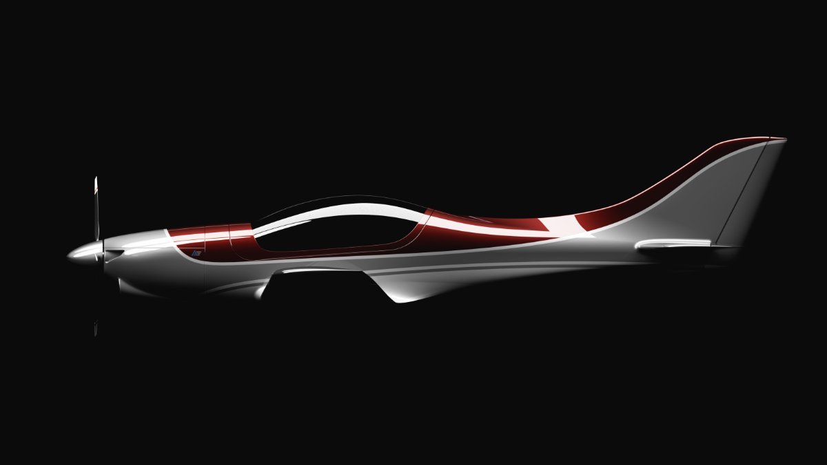
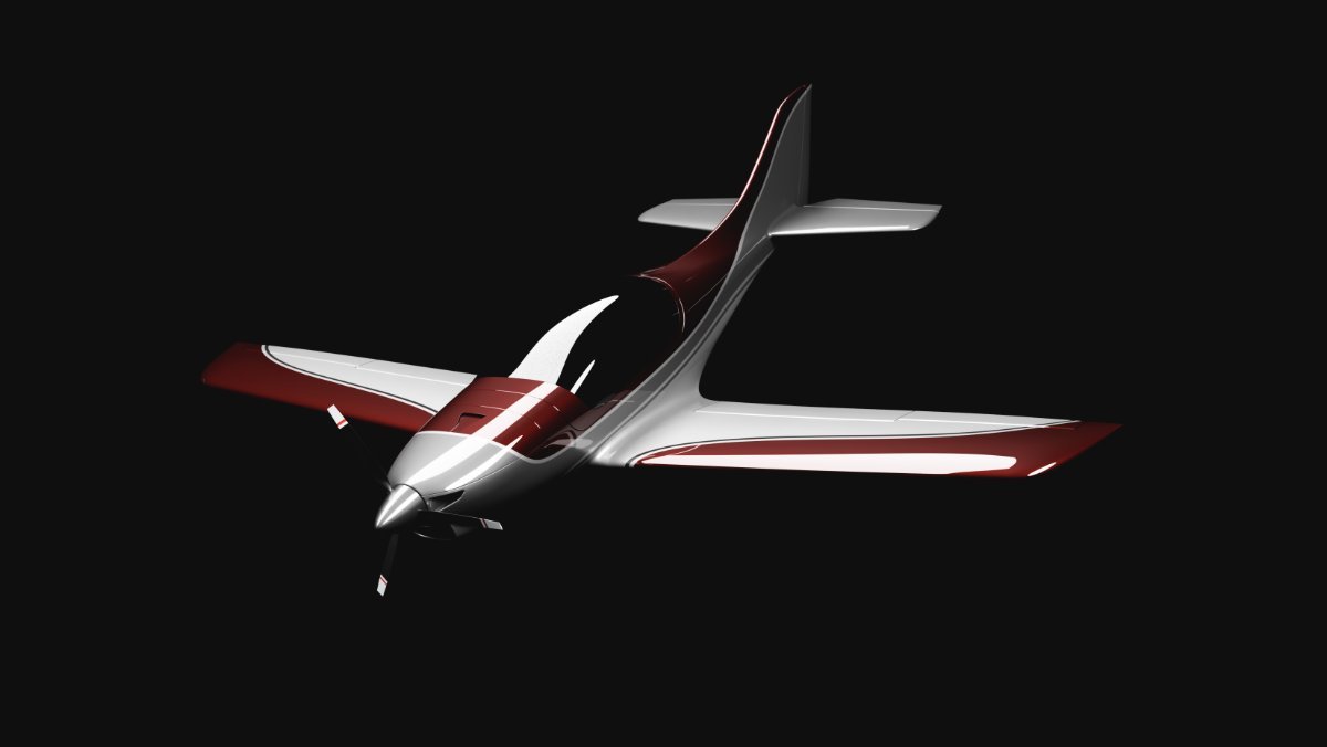
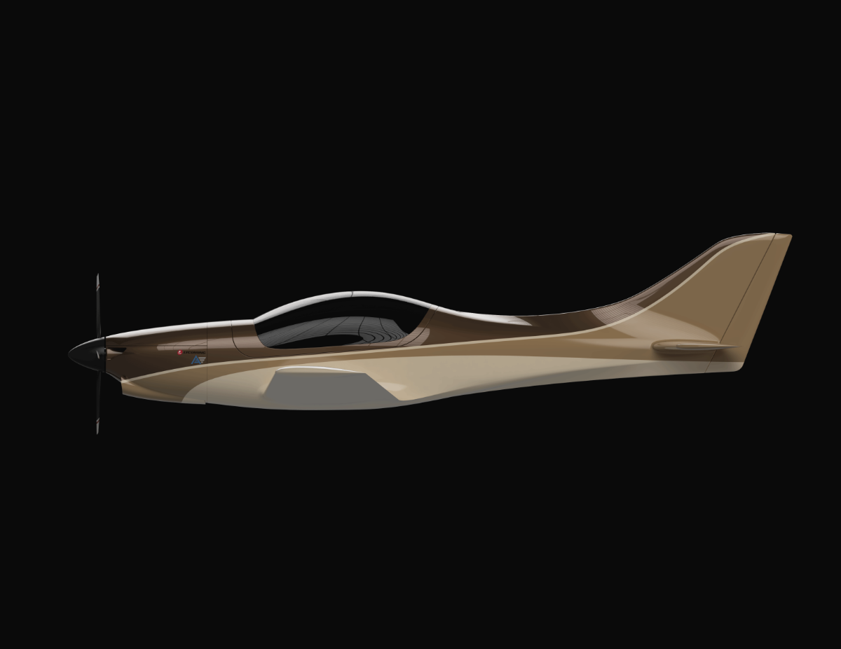
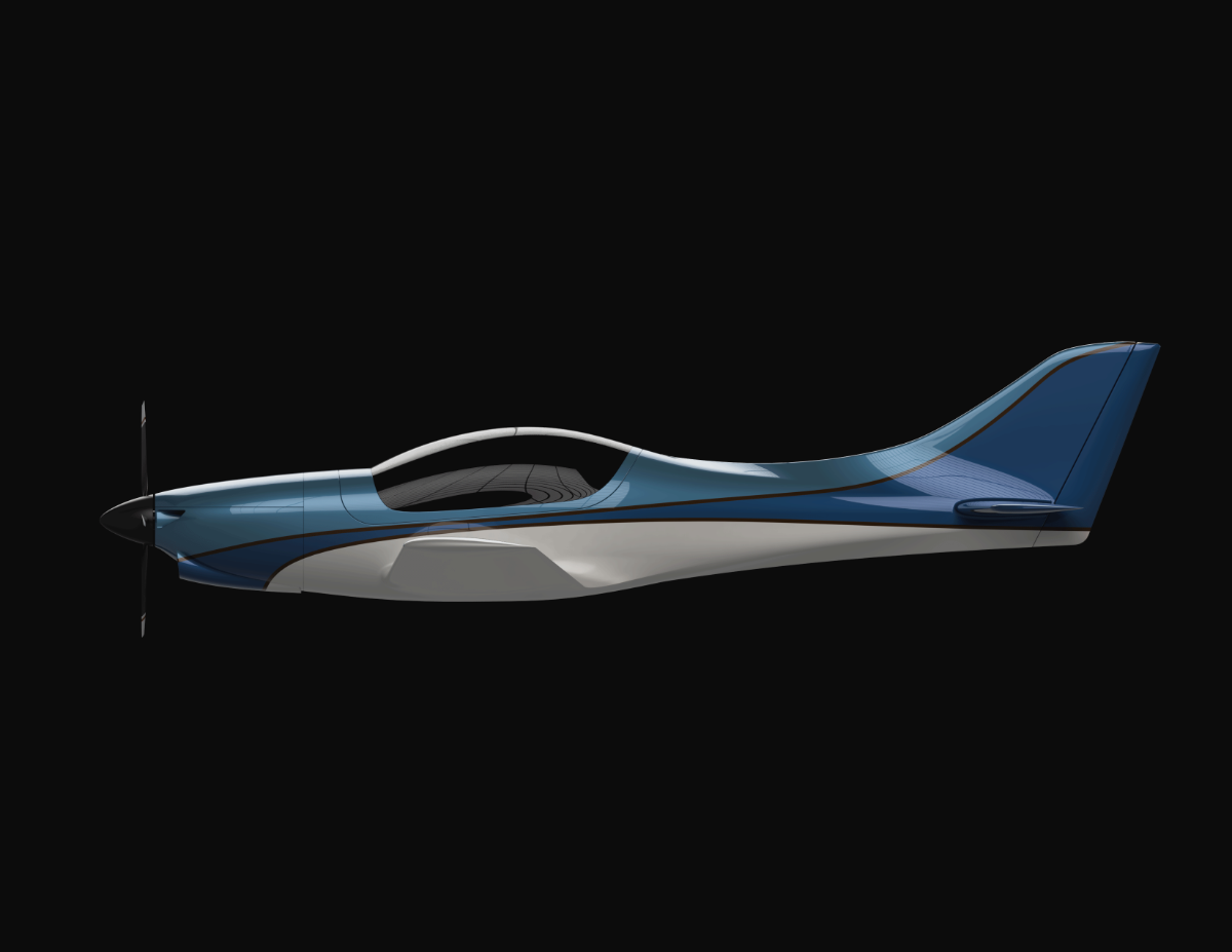
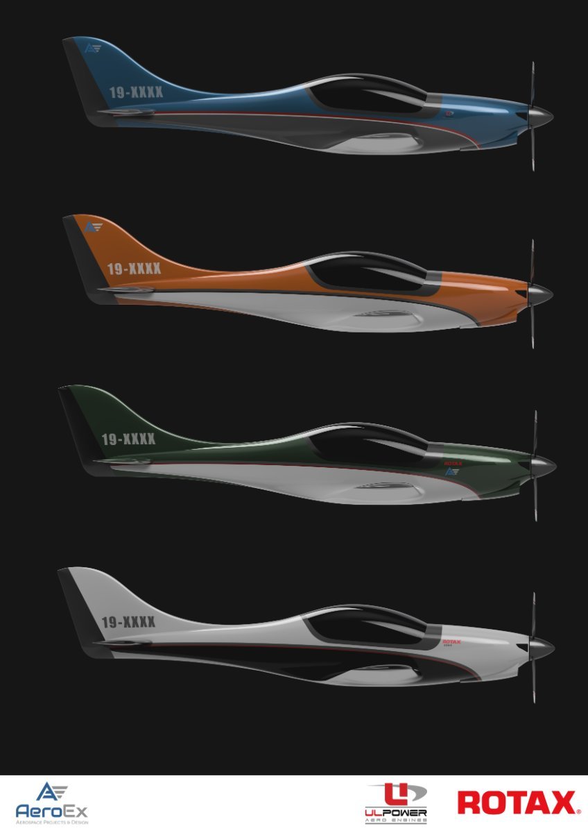
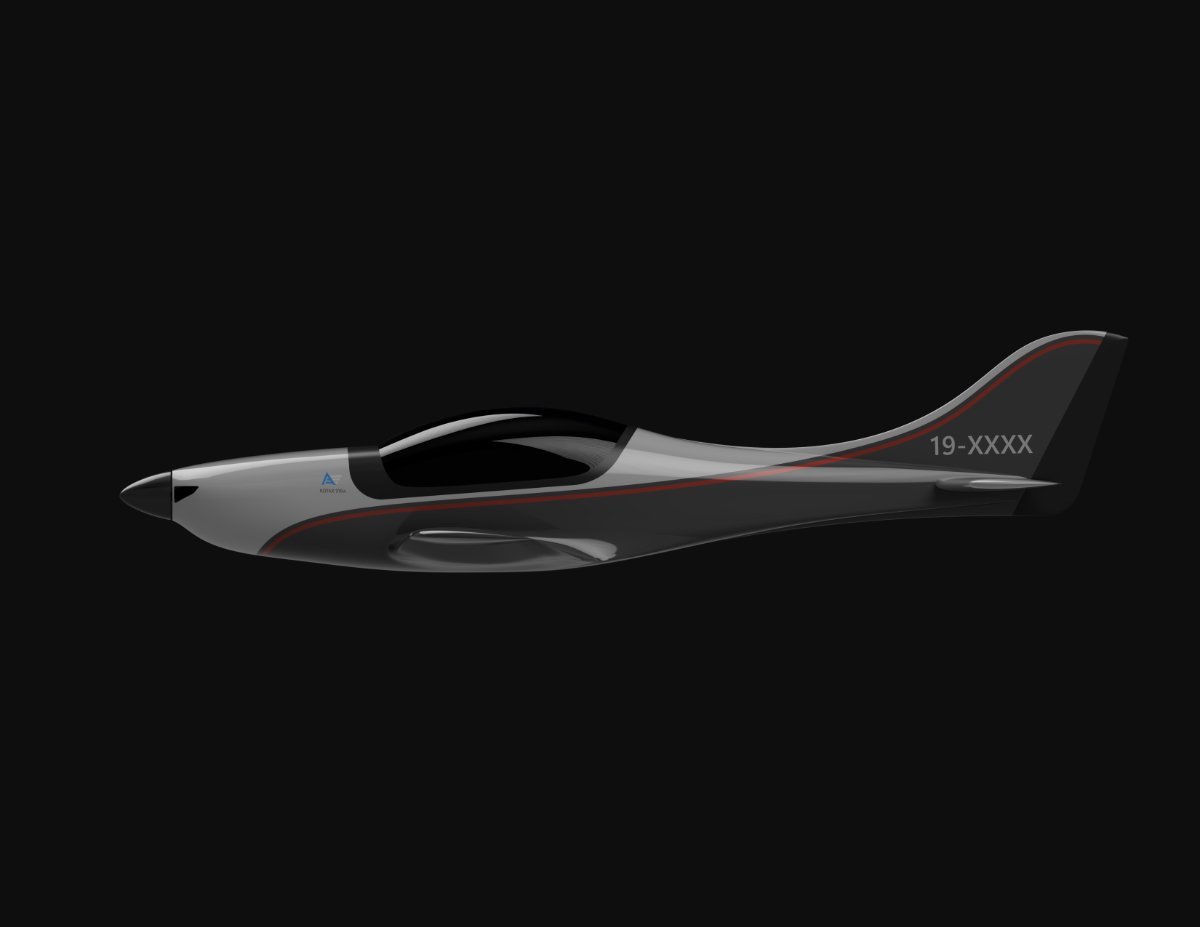
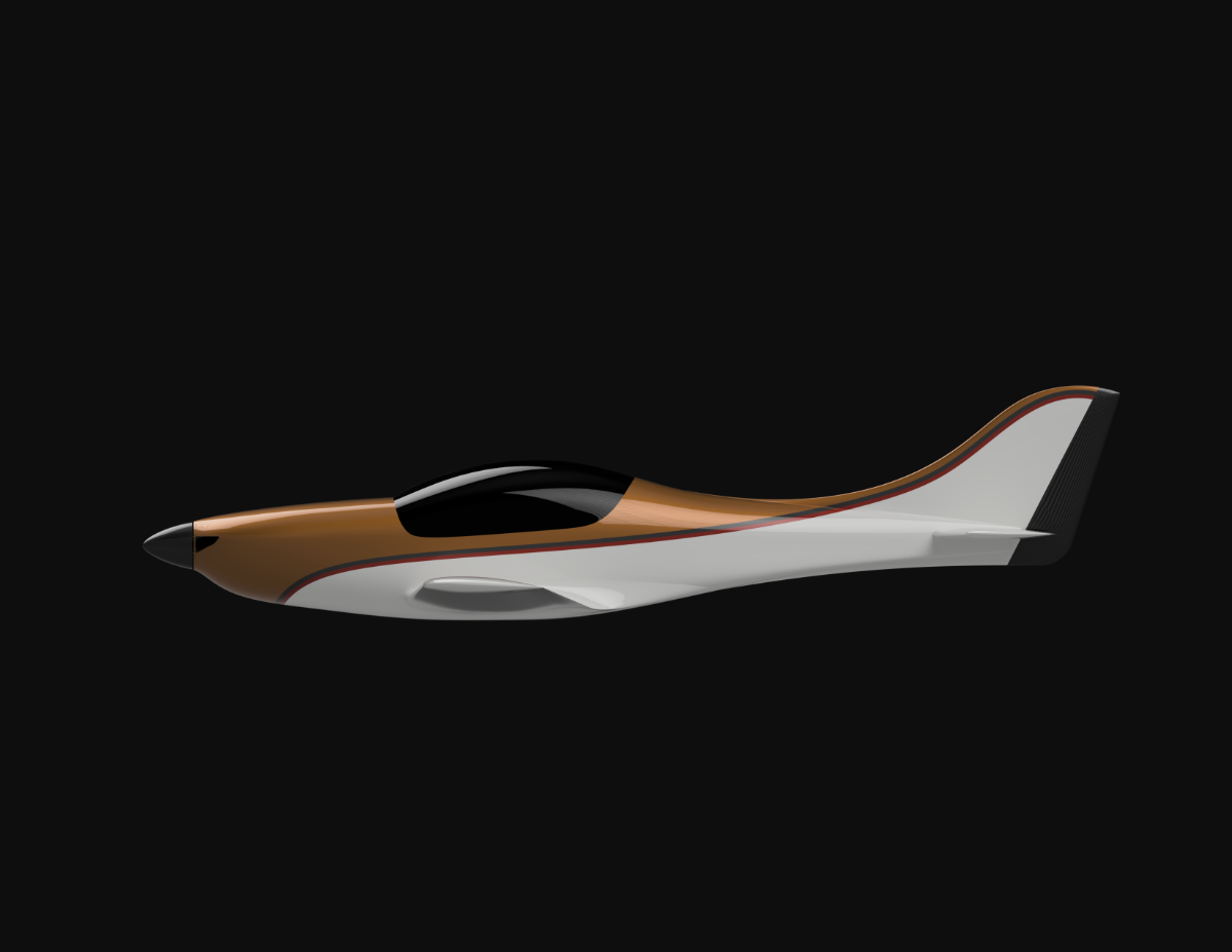
Have been burning through getting some renders done to see what looks good and so on, if you have any colour or pattern requests let me know and ill do one up and see how it looks
-
-
17 minutes ago, T510 said:
Hope you are going to offer a tail dragger option
Iv been looking at doing a taildragger version too
-
1
-
-
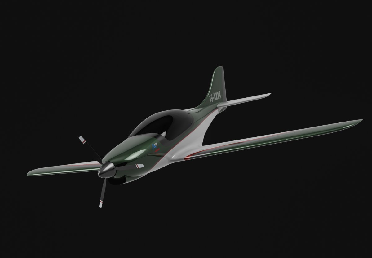
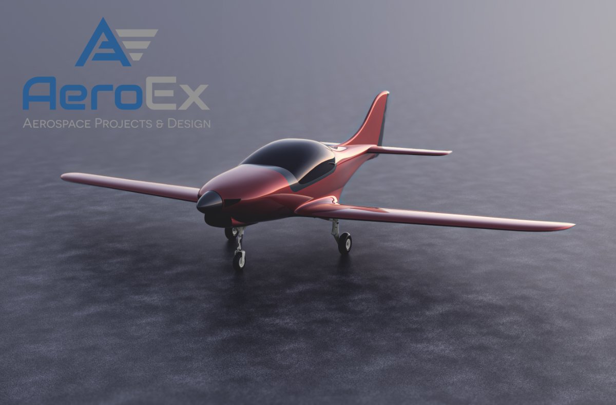
currently working on the lower intake and landing gear for retracts and fixed. you can see in one of the pics iv incorporated landing gear
-
Thought I'd do a little update.
Started from scratch on this project for the 3rd time now, as I have learnt and progressed in CAD and requirements over time I completely redesigned it. its getting pretty much into its final stages for the exterior, really happy with how it looks.
Widened Fuselage, Changed the Airfoil and wingspan, complete tail redesign, canopy and cockpit space and cowel assembly, its slightly longer, looks similar to the original design which i wanted but was a complete redo.
Still have a long way to go, and going to have a new name/designation for it
-
2
-
 1
1
-
-
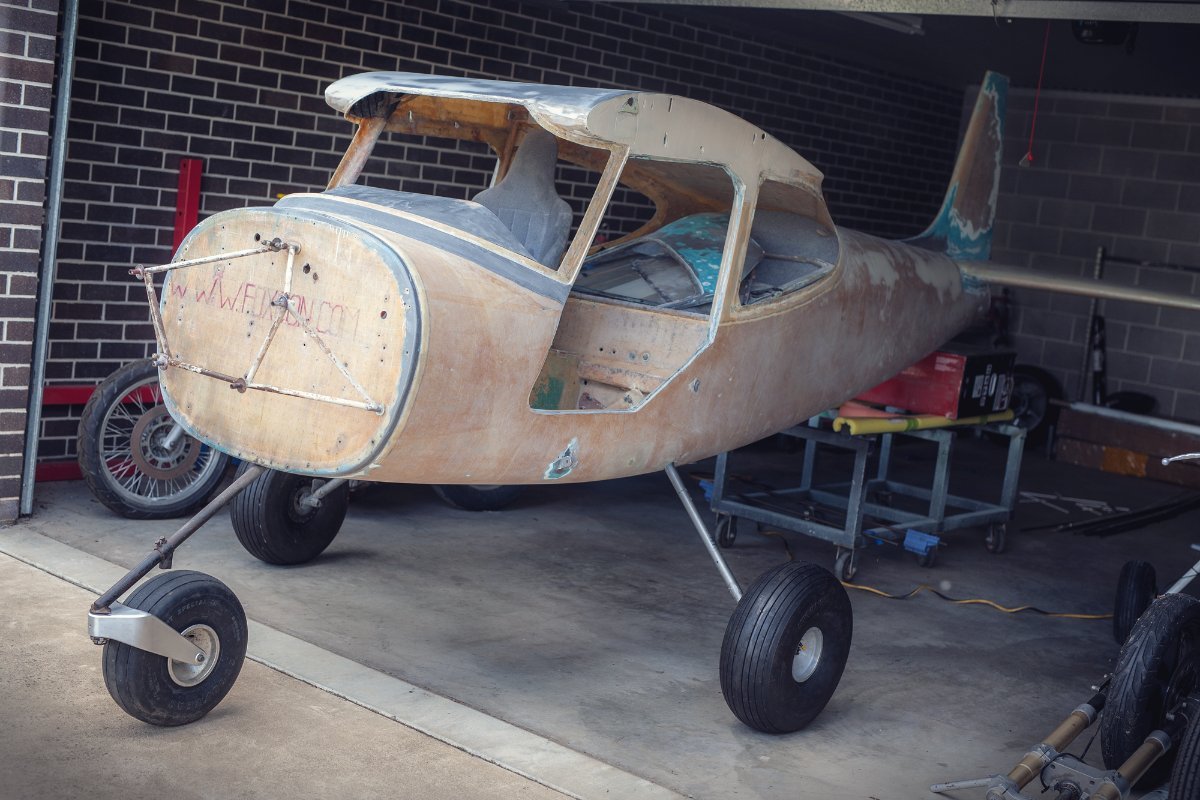
Got the foxcon up on its legs, new front undercarriage and bigger tyres looks good....very happy with it
-
6
-

.jpg.c5837f52663b363ccf7d090d1d273726.jpg)
.jpg.9f7bf159b4182f4cb217551740f7c7a9.jpg)
Crash after 3D printed air intake collapses. Good heads up for us kit builders
in Aircraft Incidents and Accidents
Posted
Really depends on the filiments used, the Nylons and high temp stuff (PA6-CF, PA6-HT etc) is perfectly fine for under the hood, the new ultam 1010 materials are self extinguishing and aimed at aerospace, just not enough saturated knowledge or experience yet around these products